40
Electrical
System
Tractors,
Lawn
and
Garden
-
110
a
nd
112
5-2
General
Information
SM-
2059
-(Apr-57)
PRINCIPLE
OF
OPERATION
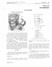
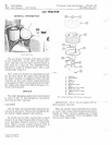
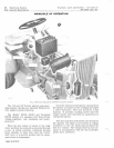
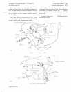
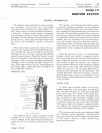
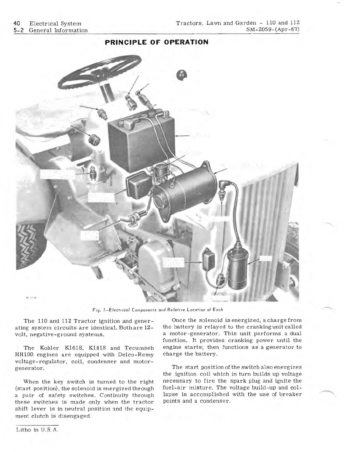
Fig.
I-Electrical
Components
and
Relative
Location
of
Each
The
110
and
112
Tractor
ignition
and
gener-
ating
system
circuits
are
identical.
Both
are
12-
volt,
negative-ground
systems.
The
Kohler
K161S,
K181S
and
Tecumseh
HH100
engines
are
equipped
with
Delco-Remy
voltage-regulator,
coil,
condenser
and
motor-
generator.
When
the
key
switch
is
turned
to
the
right
(start
position)
,
the
solenoid
is
energized
through
a
pair
of
safety
switches.
Continuity
through
these
switches
is
made
only
when
the
tractor
shift
lever
is
in
neutral
position
3.nd
the
equip-
ment
clutch
is
disengaged.
----.....
Once
the
solenoid
is
energized,
a
charge
from
the
battery
is
relay
ed
to
the
cranking
unit
called
a
motor-generator.
This
unit
performs
a
dual
function.
It
provides
cranking
power
until
the
engine
starts;
then
functions
as
a
generator
to
charge
the
battery.
The
start
position
of
the
switch
also
energ·izes
the
ignition
coil
which
in
turn
builds
up
voltage
necessary
to
fire
the
spark
plug
and
ignite
the
fuel-air
mixture.
The
voltage
build-up
and
col-
lapse
is
accomplish
ed
with
the
use
of
breaker
points
and
a
condenser
.
Litho
in
U.S.A.


