Tractors,
Lawn
and
Garden
-
110
and
112
Engine
20
SM-2059-
(Apr-67)
Cy
linder
Head
and
Valves
-
Kohl
er
10
- 7
RI
r.
HT
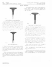
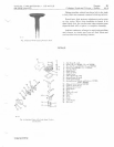
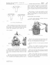
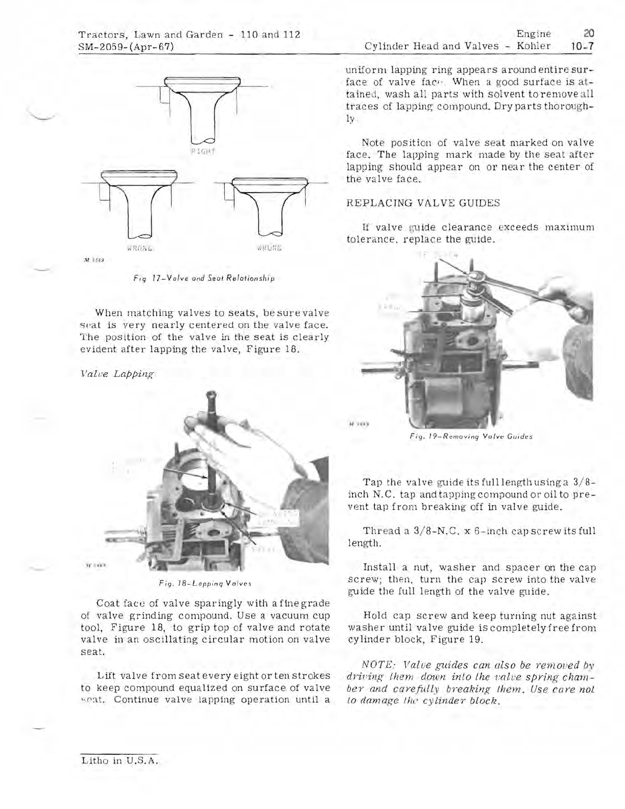
Fig
17-Valve
and
Seat
Relat
ions
hip
When
matching
valves
to
seats,
be
sure
valve
~cat
is
very
nearly
centered
on
the
valve
face.
The
position
of
the
valve
in
the
seat
is
clearly
evident
a
fter
lapping
the
valve,
Figure
lB.
Value
Lappinf{
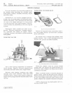
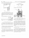
Fig,
18-Lapping
Valves
Coat
face
of
valve
sparingly
with
a
fine
grade
of
valve
p;rinding'
compound,
Use
a
vacuum
cup
tool,
Figure
1B,
to
grip
top
of
valve
and
rotate
valve
in
an
oscillating
circular
moti
on
on
valve
seat.
Lift
valve
from
seat
every
eight
or
ten
strokes
to
keep
compound
equalized
on
surface
of
valve
c
.('at.
Continue
valve
lapping
operation
until
a
Litho
in
U.S.A.
uniform
lapping
ring
appears
around
entire
sur-
face
of
valve
facl
.'
When
a
good
surface
is
at-
tained,
wash
all
part
s
with
solvent
to
remove
a
ll
traces
of
lapping
compound.
Dry
parts
thol'ol
lO'h
-
ly
Not
e
pOSition
of
valve
s e
at
marked
on
valve
face.
The
lapping
mark
made
by
the
seat
after
lapping
should
appear
on
or
n
ea
r
the
center
of
the
valve
face.
REPLACING
VALVE
GUIDES
If
valve
gu
ide
clearance
ex
ceeds
maximum
tolerance.
replace
the
guide,
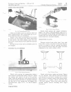
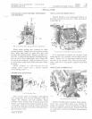
F
ig.
19-Rcmo
v
ing
Val
ve
Guides
Tap
the
valve
guide
its
full
I
en
i-,rt
b
using
a 3/ B-
inch
N.
C,
tap
and
t
app
ing
compound
or
oil
to
pre-
vent
tap
from
breaking
off
in
valve
guide.
Th
r
ea
d a 3/
8-N.
C, x 6 -
inch
cap
s
cre
w
its
full
length.
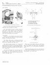
Install
a
nut,
washer
and
sp
acer
on
the
cap
screw;
then,
tUrn
the
ca
p
SCrew
into
the
valve
guide
the
full
leng·th
of
the
valve
guide.
Hold
cap
SCrew
and
keep
turning
nut
against
washer
until
valve
gUide
is
completelyfr
e
efrom
cylinder
blOCk,
Figure
19.
NOTE:
Valve
guides
can
also
be
renlOl
.'
ed
by
dririnp:
them
down
into
the
valve
spY/n
f{
cham-
bey
and
carefunv
breakinf{
them.
Use
co
re
not
to
damage
the
cylindey
block.


