Tractors,
La wn
and
Garden
-
110
and
112
Engin
e
20
SM-2059-(Apr-67)
Cam
s
haft,
Tappets
and
Governor
-
Tecums
eh
40-3
--------
~~--
~
--------------------
-----
RE
PA
IR
REMOVING
CA
MSHAFT
AND
TAP
PE
TS
.1\-1
6/yfj
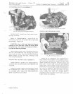
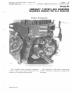
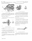
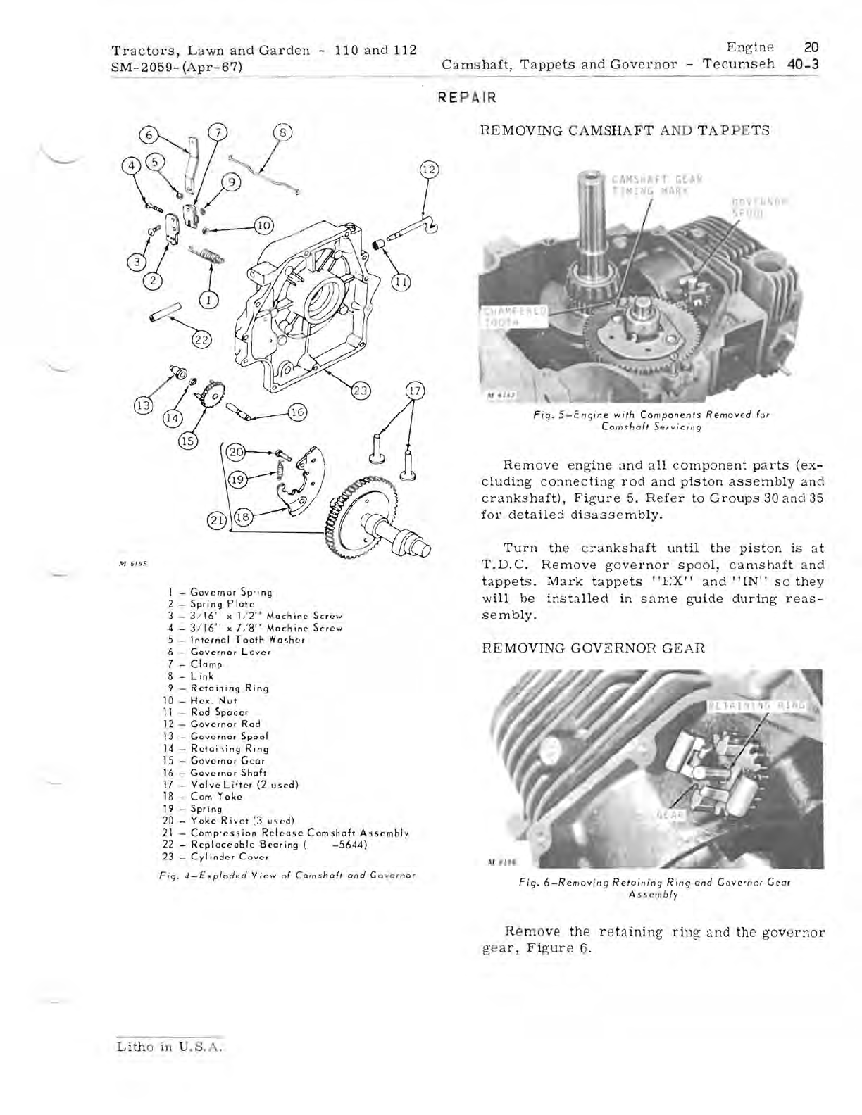
Fig.
5
-Engine
with
Companenls
Removed
(or
Camshafl
Servicing
Re
move
e
ngine
and
all
component
parts
(ex-
cluding
connecting
rod
and
piston
assembly
and
crankshaft),
Figure
5.
Ref
e r
to
Groups
30
ancl35
for
detailed
disassembly.
Turn
the
c
rankshaft
until
the
piston
is
at
T.D.C.
Remove
go
vernor
spool,
camshaft
and
tappet
s .
Mark
tappets
"EX"
and"
IN"
so
they
1 -
Governor
Spring
will
be
installed
in
same
guide
during
reas-
2 -
Spring
Plate
3 - 3/
16
" x 1/
2"
Machine
Screw
sembly.
4 - 3/
16"
x
7/8"
Machine
Screw
5 -
Internal
Tooth
Washer
6 -
Governor
L e
ver
REMOVING
GOVERNOR
GEAR
7 -
Clamp
8 -
link
9 -
Retaining
Ring
10
-
Hex
.
Nut
11
-
Rod
Spacer
12
-
Governor
Rod
13
-
Governor
Spool
14
-
Retaining
Ring
15
-
Gove-rnor
Gear
16
-
Governor
Shaft
17
-
Valve
lifter
(2
used)
18
-
Com
Yoke
19 -
Spring
20
-
Yoke
Rivet
(3
u"
,d)
21
-
Compression
Release
Camshaft
Assembly
22 -
Replaceable
Bearing
(
-5644)
23
-
Cyl
inder
Cover
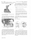
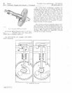
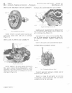
Fig.
"-Exploded
Vi
ew
o(
Comsha('
and
Go
ycrn
ar
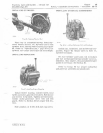
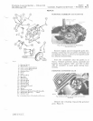
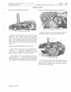
Fig.
6-Removin
g
Relaining
Ring
and
Go
vern
or GeQr
A 5
~
crn
b
ly
He mo
ve
the
r e
taining
ring
and
the
gov
e
rnor
g'
a
r,
Figur
e 6.
L
ith
o in U
.S
.A.


