40
Tractors,
Lawn
a
nd
Garden
-
110
and
112
SM-2059-
(Apr-
67)
Cuyyenl-
Voliage
-
Air
Ga
p
The
current-voltage
unit
requires
two
checks
and
adjustments:
air
gap
and
voltage
setting.
"
\t
...
..
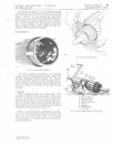
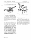
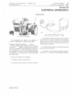
Fig
.
27
-
Current
·
Voltoge
Un
it
Air
Gop
Ch
eck
and
Adjustment
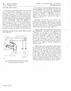
To
check
air
gap,
push
armature
down
until
the
co
ntact
points
are
just
touching,
and
th
en
measure
air
gap,
Figure
27.
Adjust
by
loos
e
nin
g
contact
mounting
screws
a
nd
raising
or
lowe
ring
contact
bracket
as
requir
ed.
Be
sure
points
are
lined
up,
and
tighten
screws
after
adjustment.
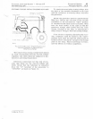
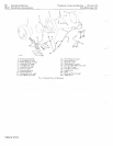
Voltage
Se
Lling
Adjust
voltage
settin
g
by
turning
adjusting
screw,
Figure
28.
Turn
screw
c
lockw
ise
to
in-
c
rease
voltage
setting
and
co
unterclockwise
to
decrease
voltage
setting.
After
each
adjustment,
set
co
ver
in
place
before
checking
setting.
CAUTION:
If
adjusting
screw
Is
turned
down
(clockwise) beyond
normal
range
required
for
adjustment,
spring
support may
fall
to
return
when
pressure
Is
relieved.
In this case,
turn
screw
counterclockwise
until
sufficient
clear-
ance develops between
screw
head
and
spring
support, then bend
spring
support upward
care-
fu
lIy
with
small
pliers
until contact I s made with
screw
head.
Final
setting of unit should always
be approached
by
Increasing
spring tension,
by
reducing
It.
In other words,
If
setting Is found
to
be
too high, unit should
be
adjusted below
re-
quired
value and then
raised
to exact setting
by
Increasing
spring
tension. Be sure
screw
Is
exerting
force
on
hanger.
Litho
in
U.S.A.
Electrical
System
Charging
System
15-1 5
'.
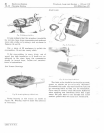
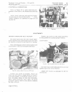
F ig .
28
-
Ad
justing
Voltage
Sett
ing
of
C u
rrent
.
Voltage
R
egu
lator
Unit
Regulator
Sp-rinf{
Replaceme1zl
When
installing
a
new
spring
on
units
of
this
type,
care
must
be
taken
to
avoid
bending
or
distorting
sprin
g
supports
or
armature
hinge.
Spring
should
preferably
be
hooked
at
the
lower
end
first
and
then
stretched
upward
by
means
of
a
screwdriver
blade
ins
e
rted
between
the
turns,
or
by
the
us
e
of
any
other
suitable
to
ol,
until
uppe
r
end
of
sprincr
can
be
hooked.
Do
not
try
to
pry
upper
end
of
s
prin
g
over
spring
s
upport.
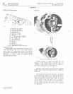
Make
connections
as
in
Fi
g
ure
28,
and
adjust
as
described
under
"Voltage
Setting"
at
left.


