'
1
1;);1-
\Apr
-0
I )
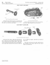
SCREWS
AND
CARR
I
ER
K
WASHERS
(BORED
HOLES
)
~
d6c
BEARING
:::::
RACE
o
o
d
~===:r=
~_,
_
~~:::~R
",
:::t=IIII
\
::D
?0
1
~
EARINC
__
BEVEL PINION BEAR I G
i'ACER CAP
SCREWS
AND
__
"
a--
,
--DR
IVE BLOCK
LOCK
WASHERS
"XLE
AND
IER
,"
lU'
PIN
I
ON
(1
APPED
HOLE
F
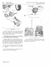
ig,
21-Dj(ferenl
iol
A
ssembly
- TlO Tr
oc/
or.
( .3571)
toe
';
'
~l
A'
W
~~,~
lR
:. ',S 'I
I~,
II
It
,
PI'.
ASS
EMBLY
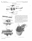
DIFFERENTIAL
AS
SEM
BLY
RING
_DRIV
E BLOCK
GEAR
BEARING
SPACE
••
-.-
, - -
mEL
"",0"
i\
lC
-
')
M
SlJ'
F
ig
22-
D
if/c
r
enliol
Ass
embly,
110
Tro
c
lors
(
Ref
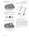
e r
to
page
20-10
and
inspect
bev
el
pinion
ge
ars
bef
or e
assembling
differential.
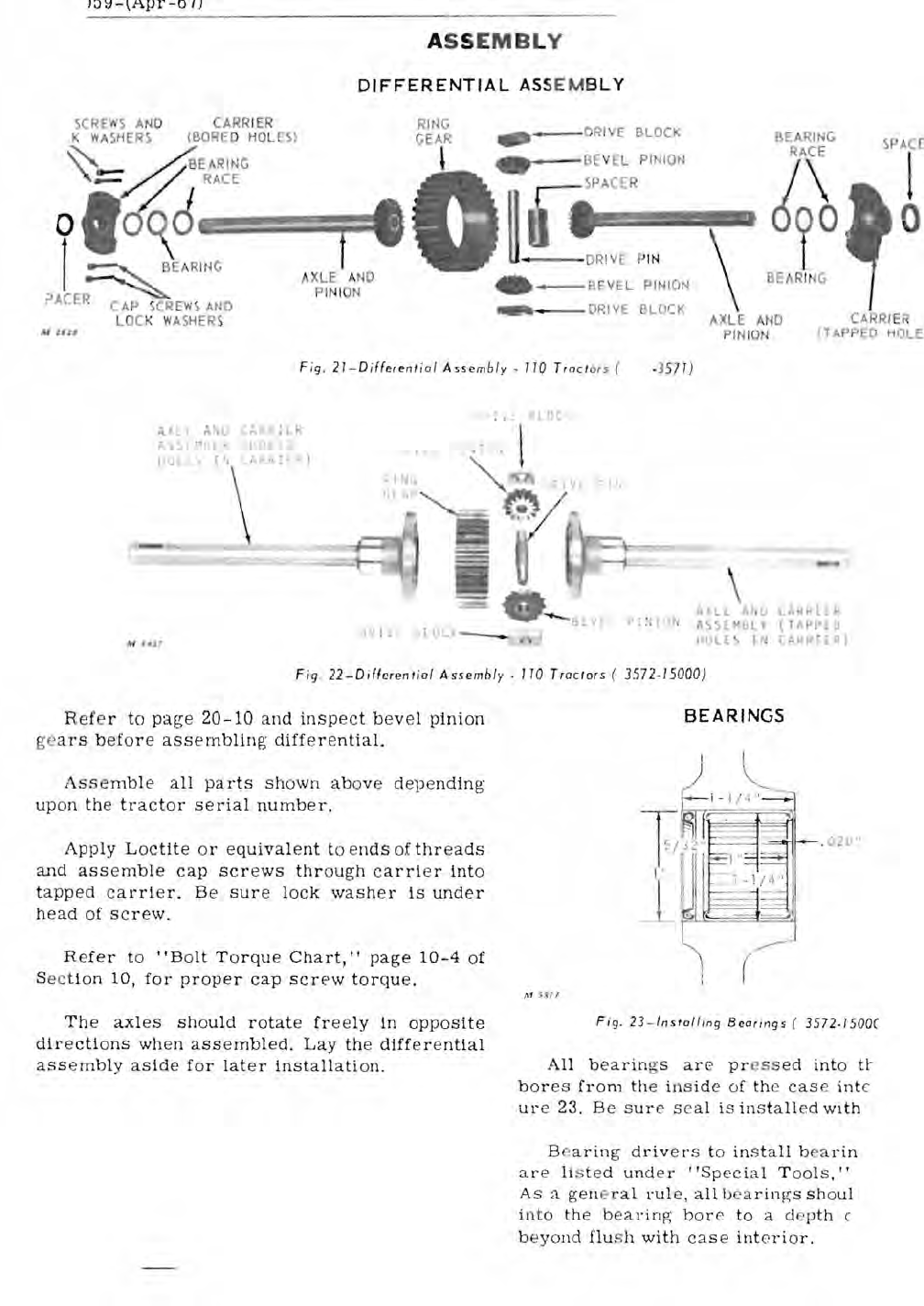
Ass
em
bl
e
all
parts
shown
above
dep
e
nding
up
on
th
e
tr
actor
se
rial
number,
Apply
Loctite
or
equivalen
t to
en
ds
of
threads
and
assemble
cap
s c r
ews
thr
oug
h
ca
rri
e r into
tapped
carr
i
er.
Be
sure
l
oc
k
washe
r
is
under
head
of
screw.
Refer
to
"B
o
lt
T o
rqu
e
Chart,"
page
10-4
of
Sect i
on
10,
for
prope
r
cap
screw
torque.
The
axles
should
r
otate
fr
ee
ly
in
oPPosi
te
dir
ec
tions
when
assembled.
Lay
th
e
differential
assembly
aside
fo
r
later
installati
on.
"
Ll
A"J
l.:'KHI£R
P:~IO~ S.l~bL
(TAPPlO
H
L[
I i
(A~R
rR)
3572
-
15000)
BEARINGS
l--
-
-j
- 9
1r-
-,
02
(j
"
(
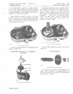
Fi
g.
23-l
n
sloll;og
Beorings
(
3572
. 1500C
All
b
ear
ings
are
pr
ess
ed
into
U-
bor
es
from
the
in
si
de
of
th
e
case
inte
ur
e 23.
Be
sure
sea
l
is
inst
alled
with
Baring
drivers
to
install
bea
rin
a r e
li
s
ted
under
"Special
T
oo
l
s,
"
As
a
ge
ne
ral
rul
e,
all
be
aring
s
sh
o
ul
into
th
e
bearing
bore
to
a de
pth
(
b
eyond
flu
s h
with
case
int
er
io
r.


