Tractors,
Lawn
and
Garden
- 110
and
112
Hydraulic
System
60
SM-2059-(Apr-67)
Pump
15-7
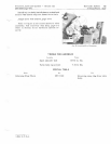
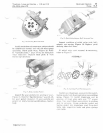
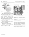
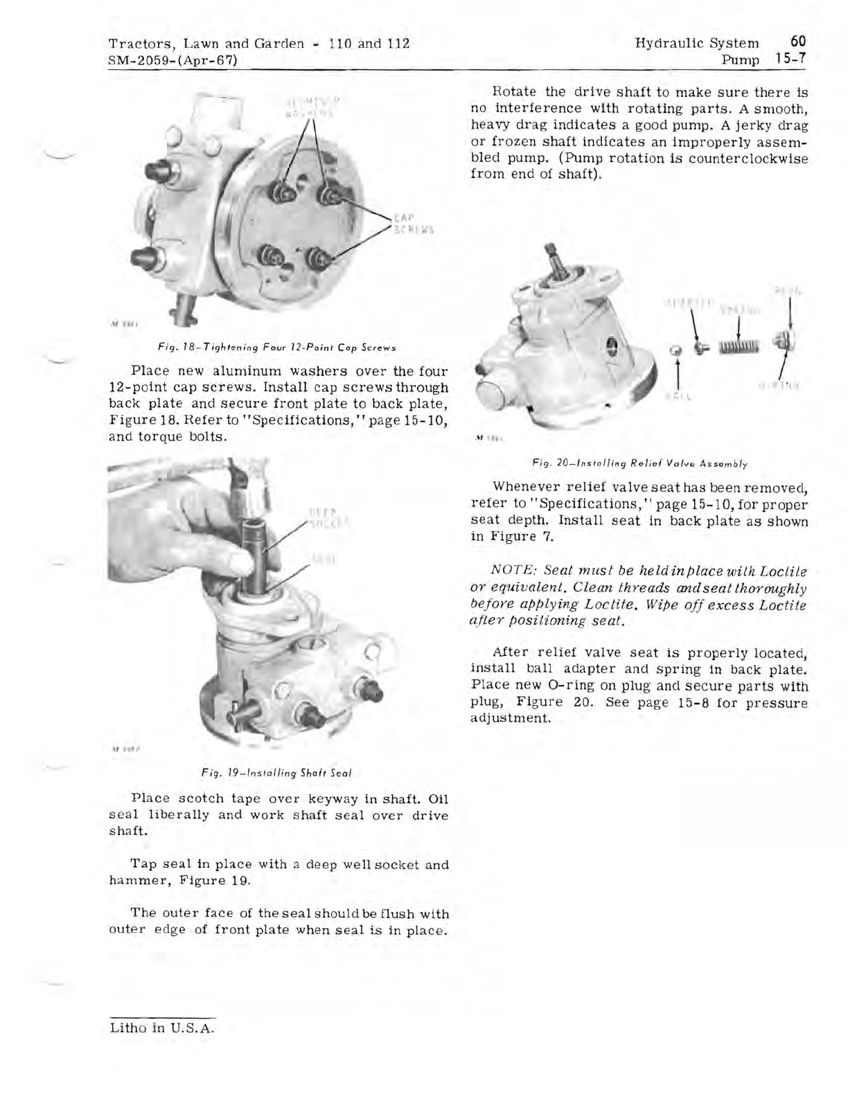
Fig.
18-
Tight
ening
Four
1
2·
Point
Cap
Screws
Place
new
aluminum
washers
over
the
four
12-point
cap
screws.
Install
cap
screws
through
back
plate
and
secure
front
plate
to
back
plate,
Figure
18.
Refer
to
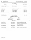
"Specifications,"
page
15-10,
and
torque
bolts.
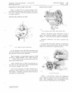
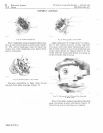
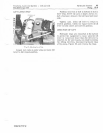
Fig.
19-1
nstolli
ng
Shaft
Seal
Place
scotch
tape
over
keyway
in
shaft.
Oil
seal
liberall
y
and
work
shaft
seal
over
drive
shaft.
Tap
seal
in
place
with
a
deep
well
socket
and
h
am
mer,
Figure
19.
The
outer
face
of
the
seal
should
be
flush
with
outer
edge
of
front
plate
when
seal
is
in
plac
e.
Rotate
the
drive
shaft
to
make
sure
th
e
re
is
no
interference
with
rotating
parts.
A
smooth,
h
eavy
drag
indicates
a
good
pump.
A
jerk
y
drag
or
froz
en
shaft
indicates
an
impr
o
perly
assem-
bled
pump.
(Pump
rotati
on
is
counterclockwise
from
end
of
shaft).
,.
Lit.
1
t
"
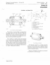
Fig
.
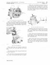
20-/nstolling
R"lief
Valve
A
ssemb
ly
When
eve
r
relief
valve
seat
has
been
removed,
refer
to"
Specifications,"
page
15-10,
for
proper
seat
depth.
Install
seat
in
back
plate
as
shown
in
Figure
7.
NOTE:
Seat
must
be
held
in
place
with
LoetiLe
or
equivalent.
Clean
threads
and
seat
thoroughly
befoye
applying
Loetite.
Wipe
off
excess
LoeWe
after
positionin
g
seat.
After
relief
valve
seat
is
properly
located,
install
ball
adapter
and
spring
in
back
plate.
Place
new
a-ring
on
plug
and
secure
parts
with
plug,
Figure
20.
See
page
15-
8
for
pr
es
sure
adjustment.
Lith
o in
U.S.A.


