20
Engine
Tractors,
Lawn
and
Garden
-
110
and
11
2
40-6
Camsh."lft, T a
ppets
and
Go
vern
or - T
ec
um
se
h
SM-
20
59-
(A
pr
-67)
INSTALLING
BREAKER
CAM
ON
CAM
SHAFT
INS
TALL
ING GOVERNOR HOD AND
LEVER
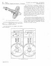
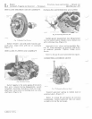
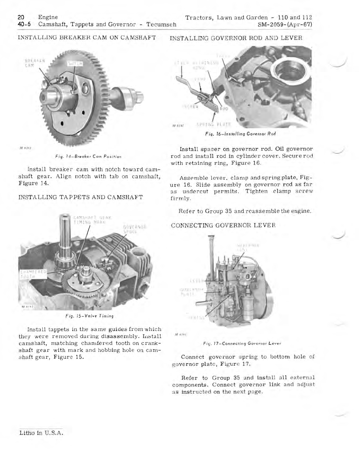
Fig.
14-Breaker
Cam
Po
si
,ian
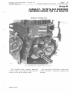
Install
breaker
cam
with
notch
toward
ca
m-
shaft
gear.
Align
notch
with
tab
on
cam
s
haft,
Fig
u
re
14.
INS
TALLING
TAPPETS
AND
CAMSHAFT
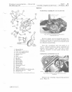
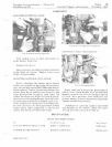
Fig
.
15-Valve
Timing
Install
tappets
in
the
same
g'Uides
from
which
th
ey
were
removed
during
disass
e
mbly.
I[lstall
camshaft,
matching
c
hamfel'cd
tooth
on
crank-
shaft
gear
with
mark
and
hobbing
hole
on
cam-
s haft
gear,
Figur
e
15.
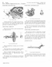
F ;9.
16-ln
s
ta!fing
Governo
r Rod
Install
s p
ac
er
on
governor
rod.
Oil
g
overnor
rod
a
nd
inst
a
ll
rod
in
cylind
r
cover.
Se
cure
r
od
with
retaining
rin
g,
Figu
r 16.
Assemble
lever.
clamp
and
sprin
g
plate,
Fi
g-
ure
16.
Slide
assembly
on
governo
r
rod
as
f
ar
as
undercut
permits.
Tighten
clamp
SC
I'
W
firmly.
Re
fer
to
Group
35
and
r
ea
ssemble
the
.!
gi
ne.
CO
NN
ECTIN
G
GO
V
ER
N
OR
LEVER
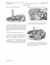
Fie;.
17-Connec,in9
Gov
e
rn
or
Lev",
Conn
ec
t
gov
rno
r s
pring
t o
bottom
hol
e
of
v;
o
vernor
plat
e ,
Fi
gu
r . 1
7.
Refer
to
Gr
oup
35
a
nd
ins
ta
ll
all
exte
r nc 1
com
p
on
e
nts
. C
onnect
governor
link
and
a
dj
ust
as
instr
ucte
d
on
th
e n
ext
pa
ge.
Litho
in U. S
.A
.


