Tractors,
Lawn
and
Garden
-
110
and
112
Hydraulic
System
60
SM-2059
-
(Apr-67)
Pump
15-1
GENERAL
INFORMATION
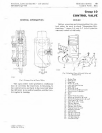
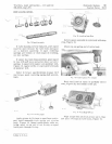
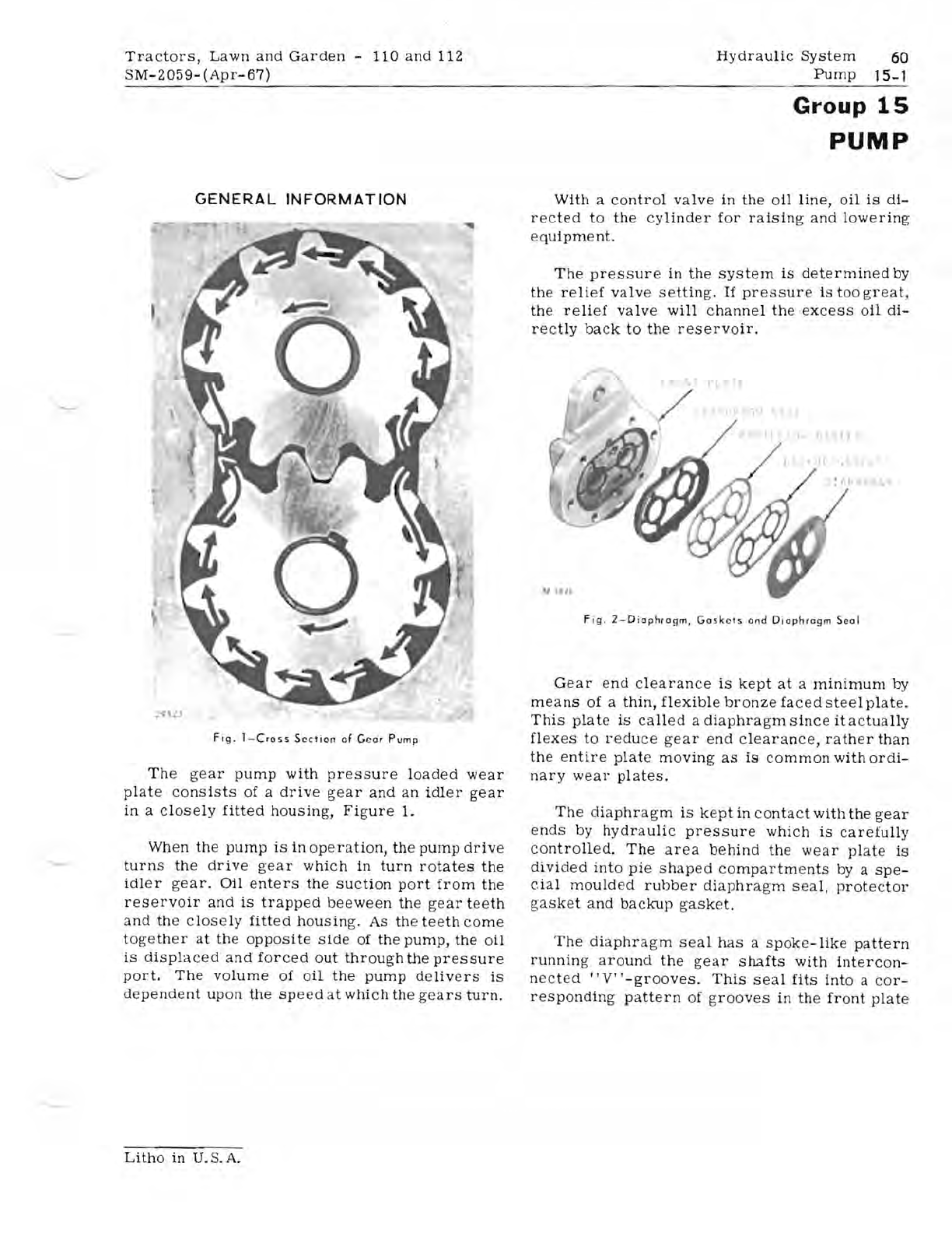
Fig.
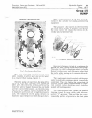
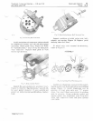
I-Cross
Section
af
Geor
Pump
The
gear
pump
with
pressure
loaded
wear
plate
consists
of a
drive
gear
and
an
idler
gear
in
a
closely
fitted
housing,
Figure
1.
When
the
pump
is
in
operation,
the
pump
drive
turns
the
drive
gear
which
in
turn
rotates
the
idler
gear.
Oil
enters
the
suction
port
from
the
reservoir
and
is
trapped
beeween
the
gear
teeth
and
the
closely
fitted
housing.
As
the
teeth
come
together
at
the
opposite
side
of
the
pump,
the
oil
is
displaced
and
forced
out
through
the
pressure
port.
The
volume
of
oil
the
pump
delivers
is
dependent
upon
the
speed
at
which
the
gears
turn.
Group
15
PUMP
With
a
con
tr
ol
valve
in
the
oil
line,
oil
is
di-
rected
to
the
cylinder
for
raising
and
lowering
equipment.
The
pressure
in
the
system
is
determined
by
the
relief
valve
setting.
If
pressure
is
too
great,
the
relief
valve
will
channe
l
the
excess
oil
di-
rectly
back
to
the
reservoir.
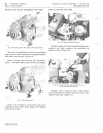
F
ig
.
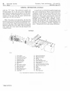
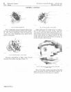
2-Diophragm,
Gosk
e
ts
and
Diaphragm
Seal
Gear
end
clearance
is
kept
at
a
minimum
by
means
of a
thin,
flexible
bronze
faced
steel
plate.
This
plate
is
called
a
diaphragm
since
it
actua
lly
flexes
to
reduce
gear
end
c
lear
ance,
rather
than
the
entire
plate
moving
as
is
common
with
ordi-
nary
wear
plates.
The
diaphragm
is
kept
in
contact
with
the
gear
ends
by
hydraulic
pressure
which
is
carefully
controlled.
The
area
behind
the
wear
plate
is
divided
into
pie
shaped
compartments
by
a
spe-
cial
mould
ed
rubber
diaphragm
seal,
protector
gasket
and
backup
gasket.
The
diaphragm
seal
has
a
spok
e
-like
pattern
running
around
the
gear
shafts
with
intercon-
nected
"V"-grooves.
This
seal
fits
into
a
cor
-
responding
pattern
of
grooves
in
the
front
plate
Litho
in
U.S.A.


