20
Engine
Tractors,
Lawn
and
Garden
-
110
and
112
10-
10
Cylinder
Head
and
Valv
es
-
Kohler
SM-2059-(Apr-67)
INSTALLING
HYDRAULIC
LIFT
ASSEMBLY
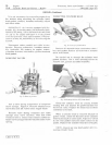
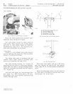
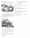
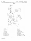
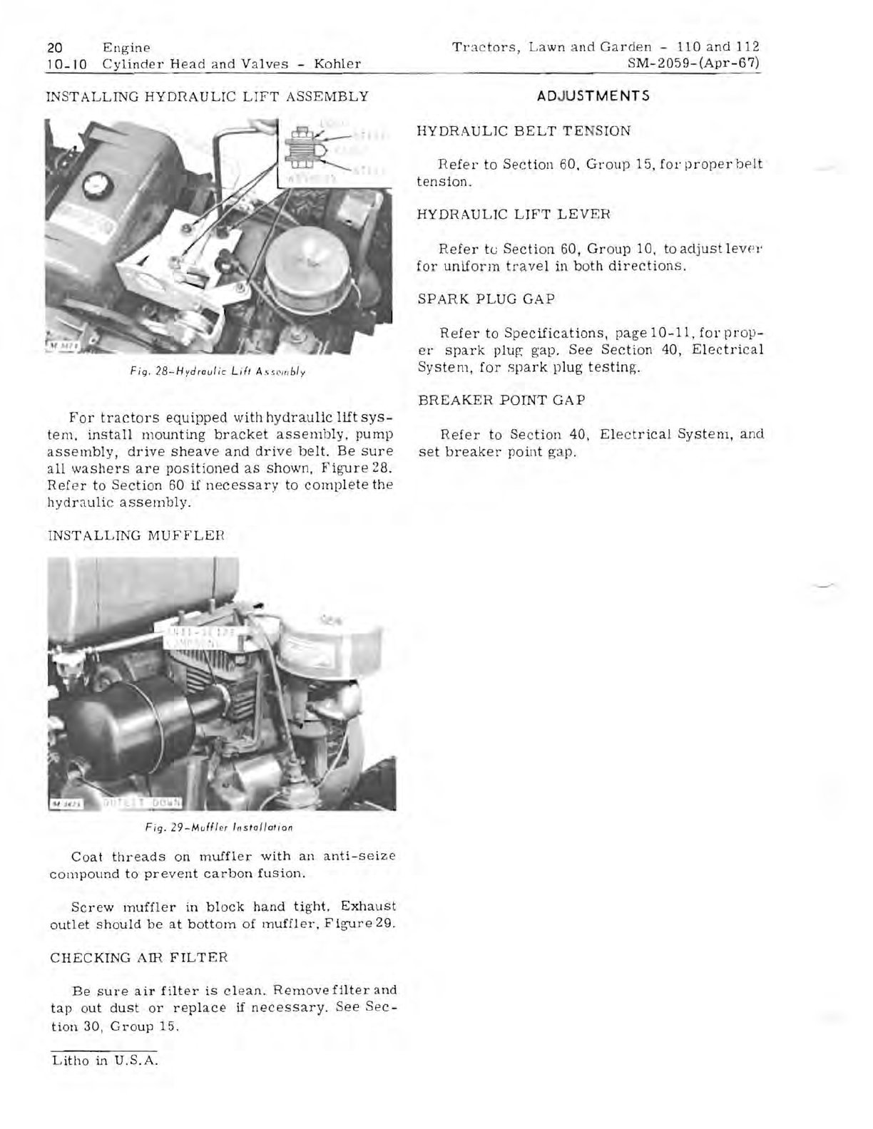
Fig
.
28-Hydrau/ic
Lif,
A
,scm
b/y
For
tractors
equipped
with
hydraulic
lilt
sys-
tem,
install
mounting
bracket
assemb
ly,
pump
assembly,
drive
sheave
and
drive
belt.
Be
sure
all
washers
are
pOSitioned
as
shown,
Figure
28.
Ref
er
to
S
ec
tion
60
if
necessary
to
comp
l
ete
the
hydr8.ulic
assembly
.
INSTALLING
MUFFLEH
AD
JUSTMENTS
HYDRAULIC
BELT
TE
SION
Refel'
to
Section
60
,
Group
15,
for
prop
er
belt
tension.
HYDRAULIC
LIFT
LEVER
Refer
tu
Section
60,
Group
la,
to
adjust
lev!'}'
for
unif
orm
tr
ave
l
in
both
directions.
SPARK
PLUG
GAP
Refer
to
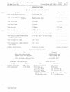
Specifications,
page
10-11,
for
p r
op-
el'
spark
pluf';
gap.
See
Section
40,
Electrical
System,
for
spark
plug
testing.
BREAKER
POINT
GAP
Refer
to
Section
40,
El
ec
trical
System,
and
set
breaker
point
ga
p.
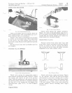
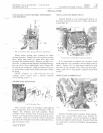
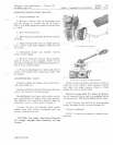
Fig.
29-Muffl
er I
nstal/alion
Coat
threads
on
muffler
with
an
anti
-s
e
iz
e
compound
to
prevent
carbon
fusion.
Screw
muffler
in
block
hand
tight.
Exhaust
outlet
should
be
at
bottom
of
muffler,
Figure
29.
CHECKING
AIR
FILTER
Be
sure
air
filter
is
cl
ean
.
Remove
filter
and
tap
o
ut
dust
or
replace
if
necessary.
See
Sec-
ti
on
30,
Group
15.
Litho
in
U.
S.A.


