Tractors,
Lawn
and
Garden
-
110
and
112
Electrical
System
40
SM-2059-
(Apr-67)
General
Information
5-3
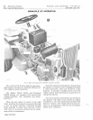
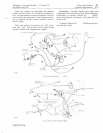
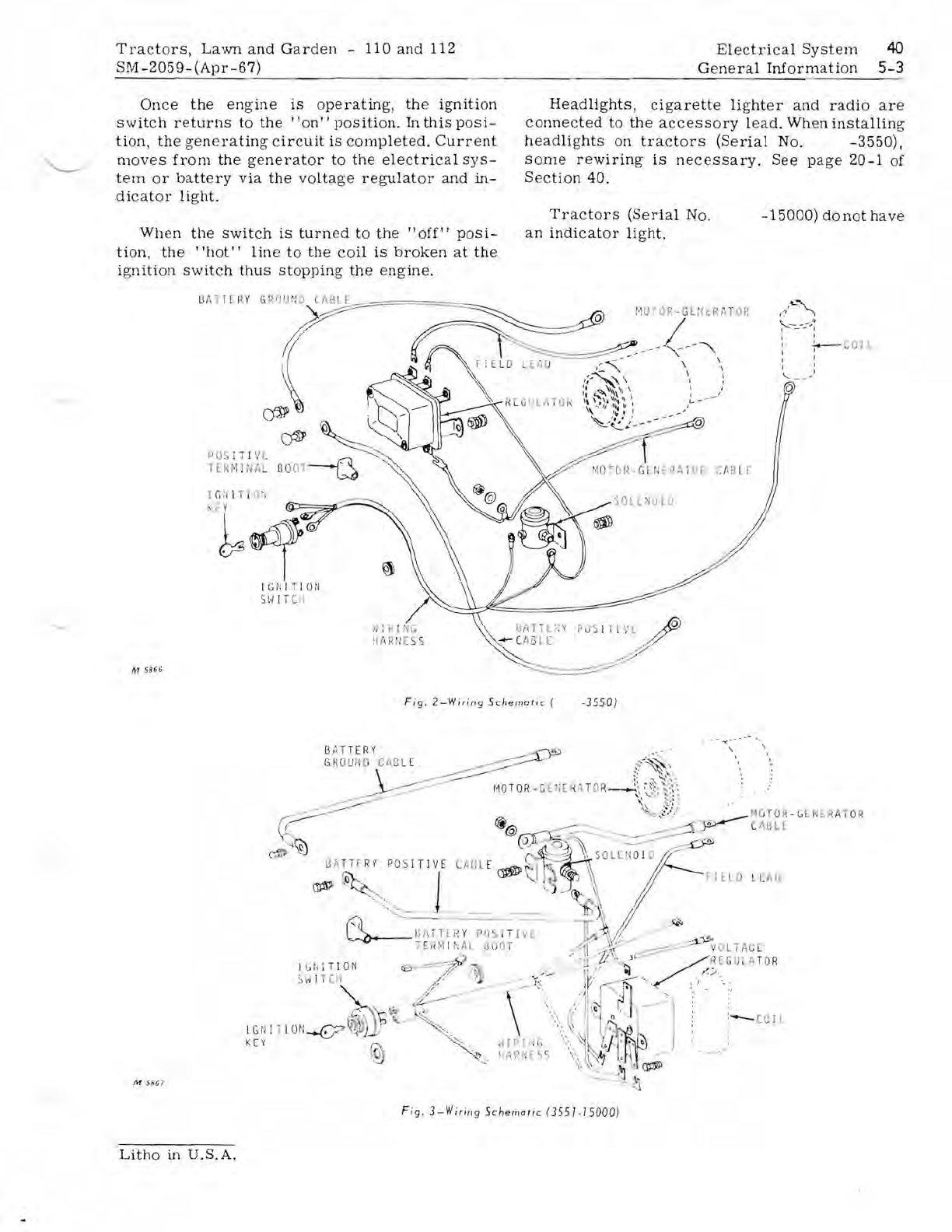
Once
the
engine
is
operating,
the
ignition
switch
returns
to
the'
'on"
position.
In
this
posi-
tion,
the
generating
circuit
is
completed.
Current
moves
from
the
generator
to
the
electrical
sys-
tem
or
battery
via
the
voltage
regulator
and
in-
dicator
light.
When
the
switch
is
turn
ed
to
the
"off"
posi-
tion,
the
"hot"
line
to
the
coil
is
broken
at
the
ignition
switch
thus
stopping
the
engine.
M 5
866
Gi\
TT
L 1< Y
POS
IT
!'
, E
HR
HI
NA
L
I
fl
!
i"I
G
11{
I
RfI
[ S
Headlights,
cigarette
lighter
and
radio
are
connected
to
the
accessory
lead.
When
installing
headlights
on
tractors
(Serial
No.
-3550),
some
rewiring
is
necessary.
See
page
20-1
of
Section
40.
Tractors
(Serial
No
.
-15000)
donothave
an
indicator
light.
17
'
~~"
i'----~
..
~
t t
:
+---
COll
t '
I I
'--
-'
Q
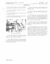
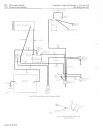
Fig.
2-Wiring
Schematic
(
·3550)
M
SS6?
fl
ATT
ER
Y
GRO
UflO CA
BL
E
I~O
TU
R
-
GEN
ER
AT
OR
C
AB
LE
Fig
.
3-Wirir19
Schernatic (35
51.75000
)
Litho
in
U.S.A.


