Tractors,
Lawn
and
Garden
-
110
and
112
Hydraulic
System
60
SM-2059-
(Apr-57)
Pump
15-9
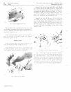
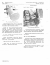
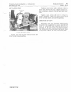
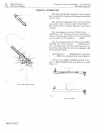
LIFT
LEVER
STOP
Fig.
23-Adjusting
Lever
Stop
Loosen
jam
nuts
on
outer
stop
and
move
lift
lever
to
full
raised
position.
Position
head
end
of
bolt
in
bottom
of
slot
in
inner
stop.
NOTE:
Be
sure
to
keep
1/
32t01
/ 16-
inch
clearance
between
the
bolt
head
and
inner
stop.
Tighten
nuts.
Allow
lift
lever
to
return
to
neutral
position.
Check
for
equal
travel
of
lift
lever
in
both
raised
and
lowered
position.
DIRECTION
OF
LIFT
Hydraulic
lines
are
connected
at
the
factory
to
permit
the
equipment
to
raise
when
the
lift
lever
is
raised
and
lower
when
the
lift
lever
is
lowered
.
If,
for
any
reason,
you
wish
to
reverse
the
lifting
direction,
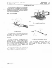
disconnect
hydraulic
lines
at
the
pump,
Figure
23,
and
reverse
the
lines.
Litho
in
U.S.
A.


