Tractors,
Lawn
and
Garden
-
110
and
112
Hydraulic
System
60
SM-
2
059-
(Apr-67)
General
Information
5-3
U
RC
l
~
'.
1111
~
t
....
tllR
/ (
PH
]
EF
VALVE
PII·jP
\
INPUT
..J
0 R
~~
PORT
"p
,"
+
Li
rT
CH
eCK I
PLU
;,GO t
o
CYLlllor R
M
58
.
19
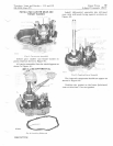
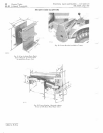
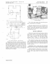
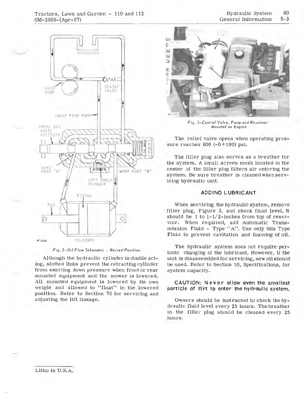
Fig.
2-0il
Flow
Schematic
-
Raised
Position
Although
the
hydraulic
cylinder
is
double
act-
ing,
slotted
links
prevent
the
retracting
cylinder
from
exerting
down
pressure
when
front
or
rear
mounted
equipment
and
the
mower
is
lowered.
All
mounted
equipment
is
lowered
by
its
own
weight
and
allowed
to
"float"
in
the
lowered
position.
Refer
to
Section
70
for
servicing
and
adjusting
the
lift
linkage.
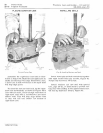
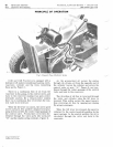
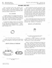
Fig.
3-Control
Valve,
Pump
and
R
ese
rvoir
Mounted
on
Engine
The
relief
valve
opens
when
operating
pr
e
s-
sure
reaches
800
(-0+100)
psi.
The
filler
plug
also
serv
es
as
a
breather
for
the
s
ys
tem.
A
small
screen
mesh
located
in
the
center
of
the
filler
plug
filters
air
ent
e
ring
the
system.
Be
sure
br
eather
is
cleaned
when
serv-
icing
hydra
u
lic
unit.
ADDING
LUBRICANT
When
se
r v
icing
the
hydraulic
system,
rem
ove
filler
plug,
Figure
3,
and
check
fluid
level.
It
should
be
1
to
1-1
/
2-
inches
from
top
of
res
er
-
voir.
When
required,
add
Automatic
Trans-
mission
Fluid
-
Type
"A".
Use
only
this
Ty
pe
Fluid
to
prevent
ca
vita
tion
and
foaming
of
oil.
The
hydraulic
system
does
not
require
per-
iodic
changing
of
the
lubricant.
However,
if
the
unit
1s
disassembled
for
servicing,
new
oil
should
be
used.
Refer
to
Section
10,
Specifications,
for
system
capacity.
CAUTION:
Never
allow even the smallest
partIcle
of
dirt
to enter the hydraulic system.
Owners
should
be
instructed
to
check
the
hy-
draulic
fluid
level
every
25
hours.
The
breather
in
the
filler
plug
should
be
cleaned
every
25
hours.
Litho
in
U.S.A.


