50
Power
Tl'ain
Tractors,
Lawn
and
Garden
-
110
and
112
10-14
Clutch,
Brake
and
Variable
Speed
Drive
SM-2059-
(Apr-67)
RE
PLACING
BRAKE
BANDS
110
Tractors
(3551-15000)
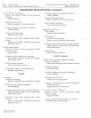
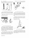
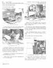
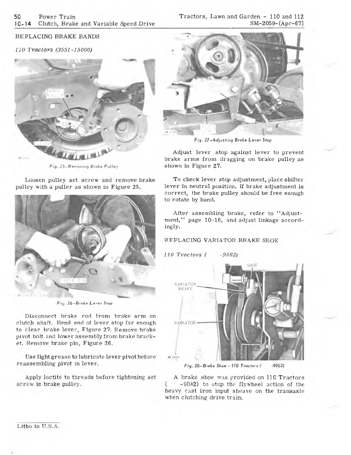
Fiq.
25-
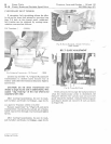
Romov,nq
Brolc
.. PlJlley
Loosen
pull
ey
set
screw
and
remove
brake
pulley
with
a
puller
as
shown
in
Figure
25,
" .
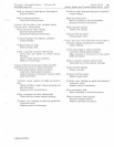
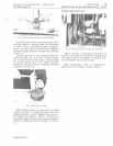
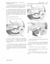
Fi
r;.
26
-B
roke
Le
ver
Stop
Disconnect
brake
rod
from
brake
arm
on
c
lutch
shaft
.
Bend
en
d of
lever
st
op
far
enough
to
clear
brake
lever,
Figur
e 27.
Remove
b
ra
ke
pivot
bolt
and
lower
assembly
from
brake
br
ack
-
et.
Remove
brake
pin,
Figure
26.
U
se
light
gr
as
e
to
lubric
, te
lever
pivot
bef
ore
reassembling
pivot
in
lever.
Apply
loetite
to
threads
before
tight
e
nin
g s et
sc
r w
in
brake
pull
ey,
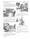
Fig
.
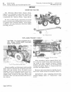
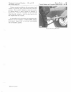
27-Adjusting
Brake
Lever
S'op
Adjust
lever
stop
against
lever
to
prevent
brake
arms
from
dragging
on
brake
pulley
as
shown
in
Figure
27.
To
check
lever
stop
adjustment,
place
shifter
lever
in
neutral
position.
If
brake
adjustment
is
correct,
the
brake
pulley
should
be
free
enough
to
rotate
by
hand,
After
assembling
brake,
refer
to
"Adjust-
ment,
t t
page
10-16,
and
adjust
linkage
accord-
ingly.
REPLACING
VARIATon
BRAKE
SHOE
110
TyocloyS
(
-9082)
v,
~11.rO",
BPM:E
VARIATOR
---ri*
I
,
'"~
'fl
O)
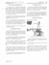
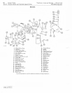
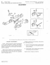
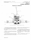
Fig.
28-Brake
Shoe
-
110
Trac'or
s (
-9082)
A
brake
shoe
','1
:
15
p
rovided
on
110
Tractors
-9082)
to
s
top
th
e'
flywheel
action
of
the
he
avy
eas
t
iron
input
sht~ave
on
the
transa
xle
when
clutching
drive
train.
Litho
in U
.S.A.


