70
Miscellaneous
Tractors,
Lawn
and
Garden
-
110
and
112
5-4
Steering
Linkage
SM-2059-
(Apr-67)
SPINDLE
BALL
JOINTS
Ill
' r !) f' jul t
A
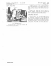
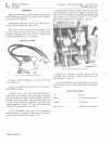
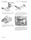
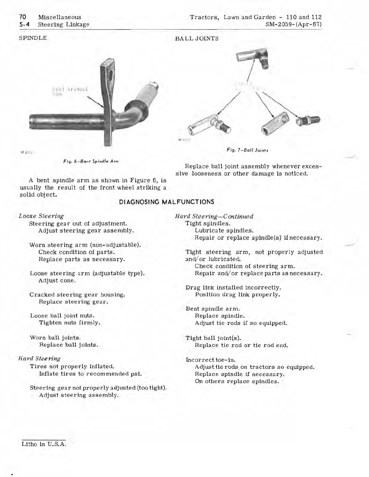
Fig.
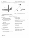
6-Bent
Spindle
Arm
A
bent
spindle
arm
as
shown
in
Figure
6,
is
usually
the
result
of
the
front
wheel
striking
a
solid
obj
ect.
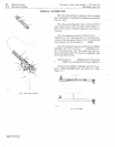
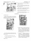
Fig.
7-801/
Joints
Replace
ball
joint
assembly
whenever
exces-
sive
looseness
or
other
damage
is
noticed.
DIAGNOSING
MALFUNCTIONS
Loose
Steering
Steering
gear
out
of
adjustment.
Adjust
steering
gear
assembly.
Worn
steering
arm
(non-adjustable).
Check
condition
of
parts.
Replace
parts
as
necessary.
Loose
steering
arm
(adjustable
type).
Adjust
cone
.
Cracked
steering
gear
housing.
Replace
steering
gear.
Loose
ball
joint
nuts.
Tighten
nuts
firmly.
Worn
ball
joints.
Replace
ball
joints.
Hard
Steering
Tires
not
properly
inflated.
Inflate
tires
to
recommended
psi.
Steering
gear
not
properly
adjusted
(too
tight).
Adjust
steering
assembly.
Hard
Steering-Continued
Tight
spindles.
Lubricate
spindles.
Repair
or
replace
spindle(s)
if
necessary.
Tight
steering
arm,
not
properly
adjusted
and/
or
lubricated.
Check
condition
of
steering
arm.
Repair
and/or
replace
parts
as
necessary.
Drag
link
installed
incorrectly.
Position
drag
link
properly.
Bent
spindle
arm.
Replace
spindle.
Adjust
tie
rods
if
so
equipped.
Tight
ball
j
oint(s).
Replace
tie
rod
or
tie
rod
end.
Incorrect
toe-in.
Adjust
tie
rods
on
tractors
so
equipped.
Replace
spindle
if
necessary.
On
others
replace
spindles.
Litho
in
U.S.A.


