SO
Power
Train
Tractors,
Lawn
and
Garden
-
110
and
112
15-14
3-Speed
Transaxle
SM-2059-(Apr-67}
M
JIll
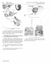
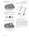
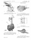
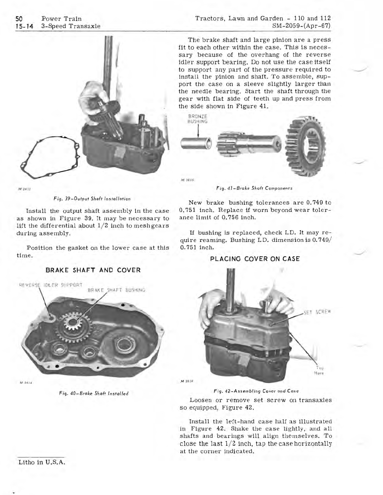
Fig.
39-0utput
Shof,
Installatio
n
Install
the
output
shaft
assembly
in
the
case
as
shown
in
Figure
39.
It
may
be
necessary
to
lift
the
differential
about
1/ 2
inch
to
mesh
ge
ars
during
assembly.
Position
the
gasket
on
the
lower
case
at
this
time.
BRAKE
SHAFT
AND
COVER
AfT
BUSHING
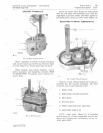
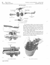
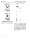
Fig.
4D-Broke
Shaft
Installed
The
brak
e
shaft
and
lar
ge
pinion
are
a
press
fit
to
each
oth
er
within
th
e
cas
e.
This
is
nece
s-
sary
becaus
e of
th
e ov
erhang
of
the
rev
e
rs
e
idl
e r
support
bearing.
Do
not
us
e
th
e
case
itself
to
support
any
part
of
the
pressur
e r e
quired
to
install
the
pinion
and
shaft.
To
assemble,
sup-
port
th
e
cas
e on a
sleev
e
slightly
larger
than
the
needle
bearing.
Start
th
e
shaft
through
the
g
ear
with
flat
side
of
t
ee
th
up
and
press
from
th
e
sid
e
shown
in
Figure
41.
BRQt
l
ZE
BU
S
HING
!
..,
IUS
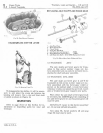
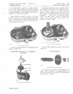
Fig.
41-Brake
Shaft
Components
New
brake
bushing
tolerances
are
0.749
to
0.751
inch.
Replace
if
worn
beyond
wear
toler-
anc
e
limit
of
0.756
inch.
If
bushing
is
replaced,
ch
e
ck
I.D.
It
may
re-
quire
reaming.
Bushing
LD.
dim
e
nsion
is
0.749
/
0.751
inch.
PLACING
COVER
ON CASE
.
\f
"J'
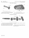
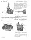
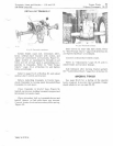
F ig.
42-Assembling
Cover
and
Case
Lo
os en
or
remov
e s et
screw
on
transaxl
es
so
equip
pe
d,
Figure
42.
Install
the
left-hand
cas e ha lf
as
illustrated
in
Figure
42.
Shake
the
cas
e lig
htly,
and
all
sh
a
fts
and
be
arings
will
align
th
e
mselves.
To
close
the
last
1/ 2 inch, tap the
case
horizontally
at
the
corn
e r
indicated.
Litho
in
U.S.A.


