Tractors,
Lawn
and
Garden
-
110
and
112
Electrical
System
40
SM-2059-(Apr-57)
Charging
System
15-3
Test
Conclusions
1.
Rated
current
draw
at
rated
speed,
as
found
in
specifications,
indicates
normal
condition
of
the
motor-generator.
2.
Low
free
speed
and
high
current
draw
in-
dicates:
(a)
Too
much
friction-tight,
dirty
or
worn
bearings,
bent
armature
shaft
or
loose
pole
shoes
allowing
armature
to
drag.
(b)
Shorted
armature.
Check
on
a
growler
after
disassembly.
(c)
Grounded
armature
or
fields.
Check
further
after
disassembly.
3.
Failure
to
operate
with
high
current
draw
indicates:
(a)
Direct
ground
in
the
terminal
or
fields.
4.
No
current
draw
indicates:
(a)
Open
field
circuit.
Check
after
dis-
assembly
by
inspecting
internal
con-
nections
and
tracing
circuit
with
a
test
lamp.
(b)
Open
armature
coils.
Inspect
the
com-
mutator
for
badly
burned
bars
after
disassembly.
(c)
Broken
brush
springs,
worn
brushes,
high
insulation
hetween
the
commutator
bars
or
other
causes
which
would
prevent
goo
d
contact
between
the
brushes
and
commutator.
5.
Low
no-load
speed
and
low
current
draw
indicates:
(a)
High
internal
resistance
due
to
poor
connections,
defective
leads,
dirty
commutator
and
causes
listed
under
No.4.
5.
High
free
speed
and
high
current
draw
in-
dicates
a
shorted
shunt
or
series
field
coil.
A
shorted
shunt
coil
can
be
determined
by
follow-
ing
para
grap
h 3,
page
15-5
under
"No
Output"
on
page
15-4
.
Ti
the
shunt
coil
performs
proper-
ly,
replace
the
series
coil.
7.
High
free
speed
and
near
normal
current
draw
indicates
an
open
shunt
coil.
Replace
the
coil
and
check
for
improved
performance.
8.
Noise
emanating
from
a
generator
may
be
caused
by
a
loose
mounting
or
drive
pulley.
It
can
also
be
caused
by
worn
or
dirty
bearings,
or
improperly
seated
brushes.
Dirty
bearings
may
sometimes
be
saved
by
cleaning
and
lubri-
cating,
but
worn
bearings
should
be
replaced.
Excessive
noise
may
result
if
the
brush
holder
is
bent
,
resulting
in
improper
seatin
g of
the
brush.
Such
a
brush
holder
must
be
replaced.
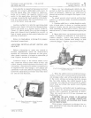
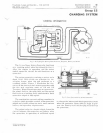
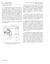
TESTING
GENERATOR
OUTPUT
{
I\r
~
.
IWL[
Rl
S
I
~lANCE
'I
tJ
L r :
'lE
r
13
DR
I
VE
M 5765
.
10
TOI!
(i
ll
oRATOR
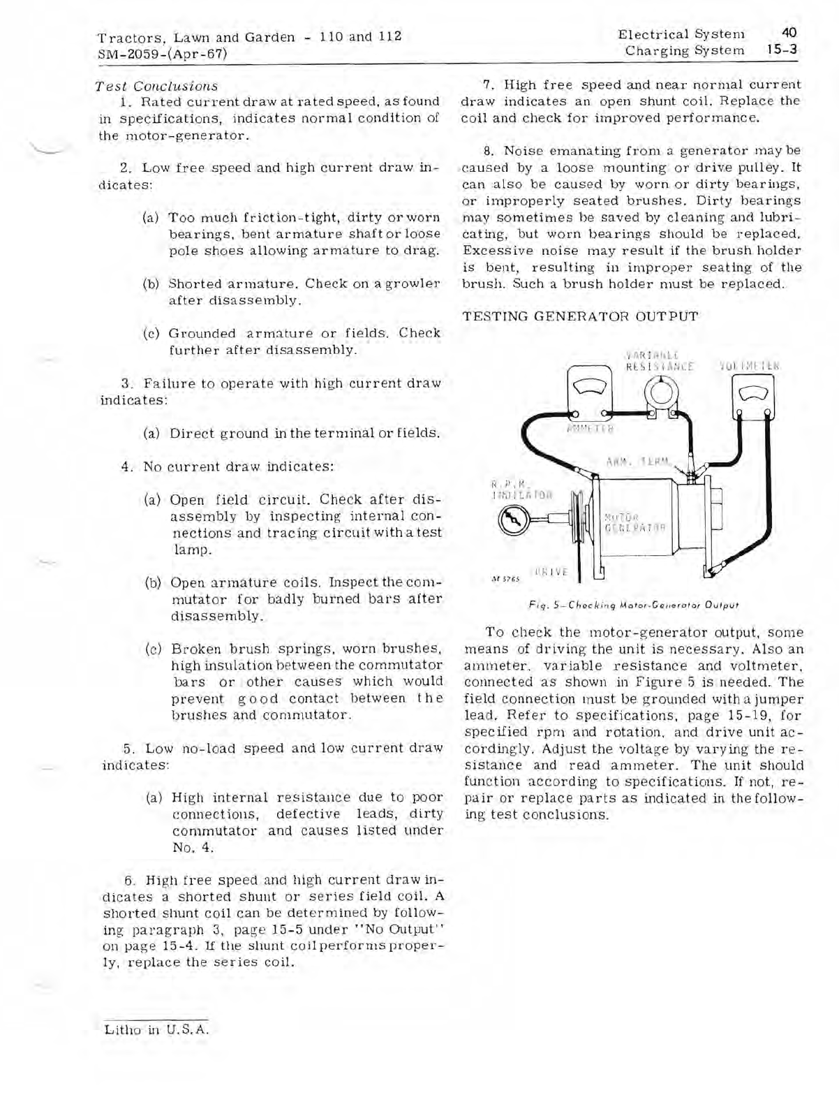
Fi
g.
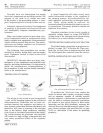
5-Checki
n9 M
oto
r-Generator
Output
To
check
the
motor-
g
enerator
output,
some
means
of
driving
the
unit
is
necessar
y.
Also
an
ammeter.
variable
resistance
and
voltmeter,
connected
as
shown
in
Figure
5
is
needed.
The
field
connection
must
be
g
rounded
with
a
jumper
lead.
Refer
to
specifications,
page
15-19,
for
specified
rpm
and
rotation.
and
drive
unit
ac-
cordin
gly.
Adjust
the
voltage
by
varying
the
re-
sistance
and
read
ammeter.
The
unit
should
function
according
to
specifications.
If
not,
re-
pair
or
replace
parts
as
indicated
in
the
follow-
ing
test
conclusions.
Litho
in U.S. A.


