70
Miscell
a
neous
Tractors,
Lawn
and
Garden
-
110
and
112
5-10
Steering
L
inkage
SM-
2059-
(Apr-
67)
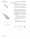
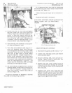
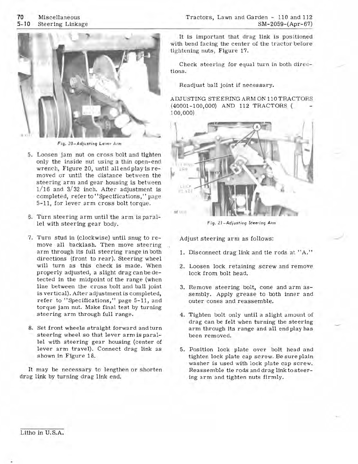
Fig
. 2
0-Ad/ustiog
L e
var
A rm
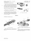
5. Loos en ja m
nut
on
cr
oss
bo
lt
and
tight
en
on
ly
the
inside
nut
usin
g a
thin
op
en
-en
d
wren
h, FibTUre
20,
until
all
end
play
is
re-
mov
ed or
until
the
distance
bet
we
en
the
steerin
g
arm
and
gear
housing
is
bet
we
en
1
/1
6
and
3/ 32
inch.
After
adjustm
e
nt
is
c
omplet
ed,
refer
to"
Specific
a
ti
o
ns,
I I p
age
5-11,
for
lever
arm
cross
bolt
torqu
e.
6.
Turn
steering
arm
until
the
arm
is
para
l-
lel
with
steering
gear
body.
7.
Turn
stud
in
(clockwise)
until
snug
to
re-
move
all
backlash.
Then
move
steering
a
rm
through
its
full
steering
range
in
both
directions
(front
to
rear).
Steering
wheel
will
turn
as
this
check
is
made.
When
properly
adjusted
, a
slight
drag
can
be
de-
te
c
ted
in
the
midpoint
of
the
range
(when
line
between
the
cross
bolt
and
ball
joint
is
vertical).
After
adjustment
is
completed,
refer
to
"Specifications,"
pa
ge
5-11,
and
torque
jam
nut.
Make
fin
al
test
by
turning
steering
arm
through
full
range.
B.
Set
front
wheels
straight
forward
and
turn
steering
wheel
so
that
lever
arm
is
paral-
lel
with
steering
gear
hOUSing
(center
of
lever
arm
travel).
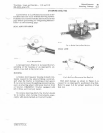
Connect
drag
link
as
shown
in
Figure
lB.
It
may
be
necessary
to
lengthen
or
shorten
drag
link
by
turning
drag
link
end.
It
is
important
that
dr
ag
link
is
positioned
with
bend
faCing
the
center
of
the
tra
c
tor
before
ti
g
ht
e
ning
nuts,
Figure
17.
Check
steer
ing
for
equ
al
turn
in
both
dir
c-
tions.
Readjust
ball
joint
if
ne
ce
ssary.
ADJUSTING
STEERING
AR
M ON
110
T RAC
TO
RS
(40001-100,000)
AND 112
TR
A
CTORS
(
100,000)
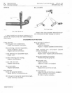
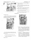
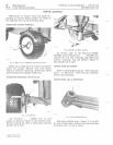
Fig.
21-Adiusting
Steering
Arm
Adjust
steering
arm
as
follows:
1.
Disconnect
drag
link
and
tie
rods
at
"A."
2.
Loosen
lock
retaining
screw
and
remove
lock
from
bolt
head.
3. Re
move
steering
bolt,
cone
and
arm
as-
sembly.
Apply
grease
to
both
inner
and
outer
c
ones
and
reassemble.
4.
Tighten
bolt
only
until
a
slight
amount
of
drag
can
be
felt
when
turning
th
e
steering
arm
through
its
range
and
all
end
play
has
been
removed.
5.
Position
lock
plate
over
bolt
head
and
tighten
lock
plate
cap
screw.
Be
sure
plain
washer
is
used
with
lock
plate
cap
screw.
Reassemble
tie
rods
and
drag
link
to
steer-
ing
arm
and
tighten
nuts
firmly.
Litho
in
U.
S.A.


