


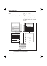

This trigger configuration is sufficient for
most instruments. More complex instru
-
ments, such as the CNT-8X, have more
ARM layers.
The ‘Wait for TRIG’ event-detection
layer is always the last to be crossed be
-
fore instrument actions can take place.
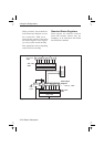
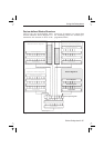
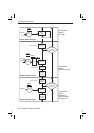
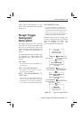
Structure of the IDLE and
INITIATED States
When you turn on the power or send
*RST or :ABORT to the instrument, it
sets the trigger system in the IDLE state;
see .
The trigger system will exit from the
IDLE state when the instrument receives
an INITiate:IMMediate. The in-
strument will pass directly through the
INITIATED state downward to the next
event-detection layers (if the instrument
contains any more layers).
The trigger system will return to the INI-
TIATED state when all events required
by the detection layers have occurred and
the instrument has made the intended
measurement. When you program the
trigger system to INITiate:CONTin
-
uous ON, the instrument will directly
exit the INITIATED state moving down
-
ward and will repeat the whole flow de
-
scribed above. When
INITiate:CONTinuous is OFF,
the trigger system will return to the IDLE
state.
n
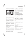
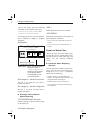
Structure of an Event-detection
Layer
The general structure of all
event-detection layers is identical and is
roughly depicted by the flow diagram in
In each layer there are several program-
mable conditions, which must be satisfied
to pass by the layer in a downward direc-
tion:
n
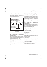
Forward Traversing an
Event-detection Layer
After initiating the loop counters, the in
-
strument waits for the event to be de
-
tected. You can select the event to be
detected by using the <layer>:SOURce
command. For example:
:ARM:LAYer2:SOURce BUS
You can specify a more precise character
-
istic of the event to occur. For example:
:ARM:LAYer:DELay 0.1
You may program a certain delay be
-
tween the occurrence of the event and en
-
tering into the next layer (or starting the
device actions when in the TRIGger
6-28 Trigger/Arming Subsystem
Using the Subsystems
IN IT [:IM M ] o r
IN IT :C O N T O N ?
IN IT [:IM M ] o r
IN IT :C O N T O N ?
No
Yes
ID L E
state
IN IT IA T E D
state
*R ST
ABORt
pon
No
Yes
Figure 6-16 Flow diagram of IDLE
and INITIADED layers.