© 2003 Alamo Group Inc.
Section 9 - 11
A-Boom (JD 6615 / 7615 Asy Instruction Manual) 07/03
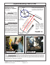
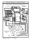
Joystick Plug (Bottom of Joystick Console)
A
J
C
K
L
F
M
H
X
B
D
E
G
N
P
R
S
T
U
V
W
X
X
1
2
3
4
5
7
6
Master Switch
Motor
Relay
X
Red
Motor Push / Pull
Switch With
Momentary Start
Grn
Yel
Red
Wht/Violet
Violet
Rocker Switch
Dbl Trigger Switches
1
2
3
4
5
6
7
8
10 AMP
Grnd
X-Output
Acc
Ign
Start
Pwr
Org/Blk
K
Y-Output
Brn/Blk
C
- Negatve
Grey/Blk
J D
Z-Output
+ Positive
B
Wht/Blk
Wht/Red
Danfoss Command
Circuit (Joystick)
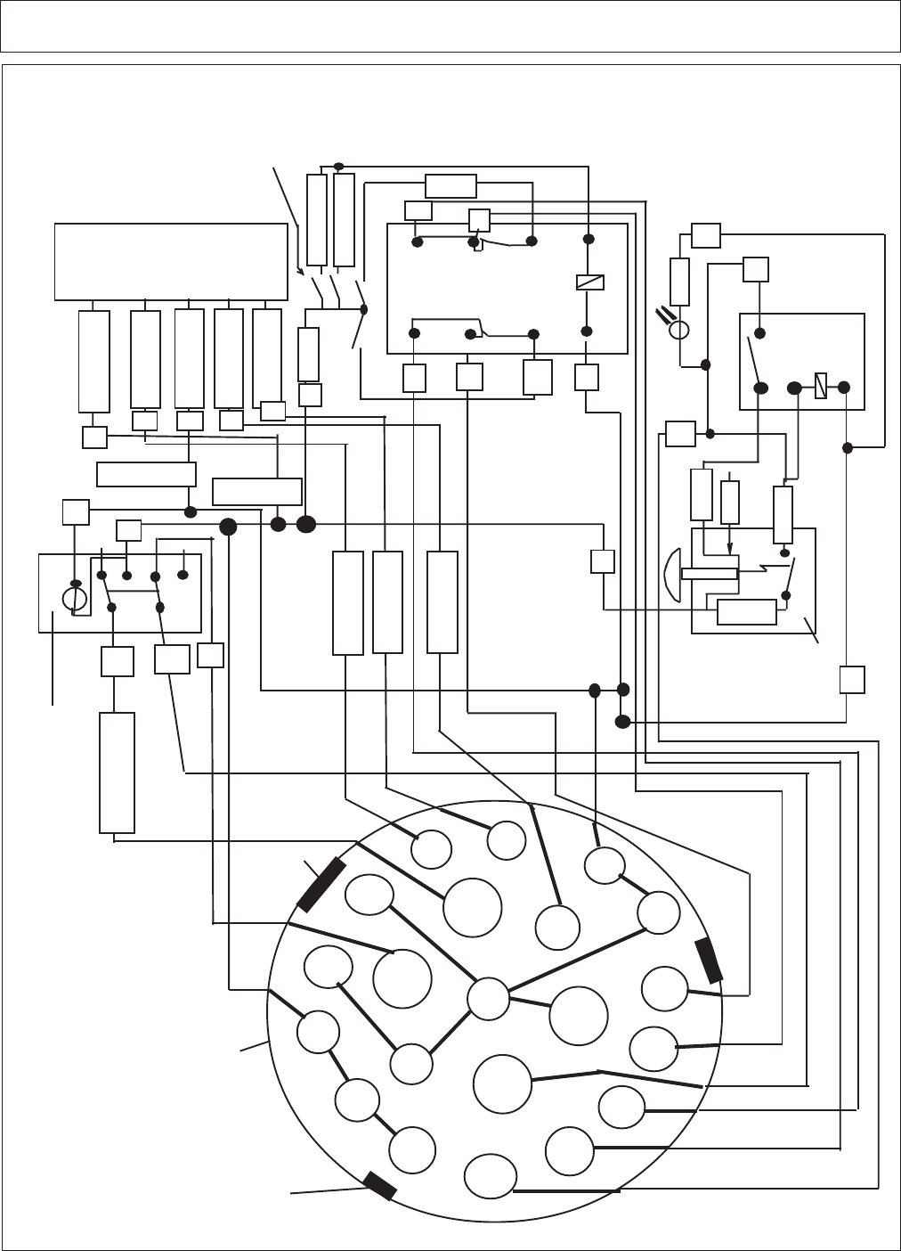
Joystick w/ Push/Pull Motor Switch & Rocker Master Switch
FIGURE 30
X
R D
D
B
GB
E
T
D
D
B
B
DJ C
K
B
T
S
P
N
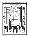
Actual Pin Location
IS SHOWN in this
Illustration
Narrow
Notch (2)
Wide
Notch
(1)


