


A-Boom (JD 6615 / 7615 Asy Instruction Manual) 07/03
© 2003 Alamo Group Inc.
Section 3 - 4
Pump / Drive Assembly Instructions
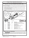
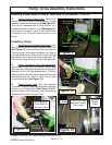
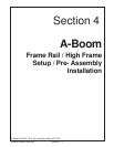
6. Install Shaft End of Driveline / Engine end.
Install the Shaft 1/2 Assembly w/ Flanged Yoke into
the Engine compartment of Tractor, install it from
the LH front Side down and under radiator. (See
Figure 6). This needs to be installed this way
because the Flange Yoke will not go through the
Crankshaft access hole in the front of the Tractor
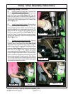
(See Figure 3). Bolt the Flange Yoke to the Pulley
Adapter using the four 7/16" X 1-1/4" Bolts (Part #
02976344), use the four Lock Washers (Part #
00022200), put Locktite on the threads of the Bolts
and install them into Pulley Adapter. To Tighten
these four Bolts, use a long extension and go
through the front Crankshaft Pulley access hole in
front of Tractor. Do Not use bolts longer than 1-1/4"
long, longer bolts will damage
Crankshaft Pulley.
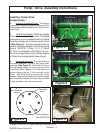
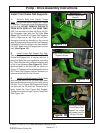
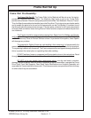
Installing Pump Mount Plate & Tube
End of Driveshaft:
1. Install Pump Mount Plate. Install Front Pump
Plate # 02976087 standard mount plate (See
Figure 7) or # 02979080 optional Pump Mount
Plate w/ Pump Guard built on. (Not Shown) use
the 2 Spacers on the JD 6615 Series, Do not install
Pump Mount Plate without using these Spacers.
The Spacers are for Tractor Hood Clearance. Insert
the 4 bolts and lock washers into Pump Mount Plate
and spacers (See Figure 7), tighten them to re-
quired Torque (See Bolt Torque Chart).
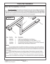
2. Driveline timeing means the universal joints
are both the same position when driveline half is slid
together. If they are not timed, it will decrease the life
of the universal joint and in some cases could cause
a vibration. (See Figure 5 on previous page)
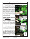
3. Install Tube End of Driveline / Pump End.
Slide the Tube half of driveshaft through Pump
Mount Plate and Tractor Crankshaft Access Hole
(See Figure 8). You will have to align the Universals
when doing this (time the Driveshaft). Slide the two
together where the Universal are in time (See
Figure 5 on previous page), this will help the
driveshaft to operate smoothly.
Figure 8
Tube End of
Driveshaft
Splined
Clamp Yoke
Figure 6
Shaft 1/2 Assembly
w/ Flanged Yoke
Left Hand front side
of Tractor
Tractor Engine
Tractor
Radiator
Figure 7
Spacer (2)
Standard Pump
Mount Plate
Shown
Standard
Pump
Mount
Plate
Shown
Installing Pump Drive Components: (continued)