


© 2003 Alamo Group Inc.
Section 3 - 3
A-Boom (JD 6615 / 7615 Asy Instruction Manual) 07/03
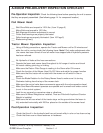
Pump / Drive Assembly Instructions
Installing Pump Drive
Components:
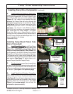
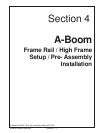
2. Access to Crankshaft Pulley. The Factory
Crankshaft Pulley will not need to be removed. The
Pulley Adapter will be bolted to the Factory Crank-
shaft Pulley.
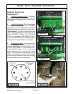
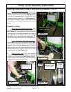
3. Install Pulley Adapter. The Pulley adapter
to be used is a round plate with 4 threaded
holes and four non-threaded holes in it. Notice
this pulley adapter will not have a center hole in
it (See Figure 4). The Non-treaded holes are
used to mount the Adapter to the Pulley using
bolts # 02979791 (10mm 1.5 P X 35mm
Gr.10.9) & Lockwasher # 00755954 (10 mm).
Do not use longer bolts to mount Pulley Adapter
to Pulley than is supplied with mounting kit.
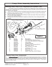
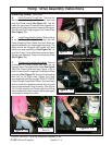
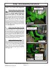
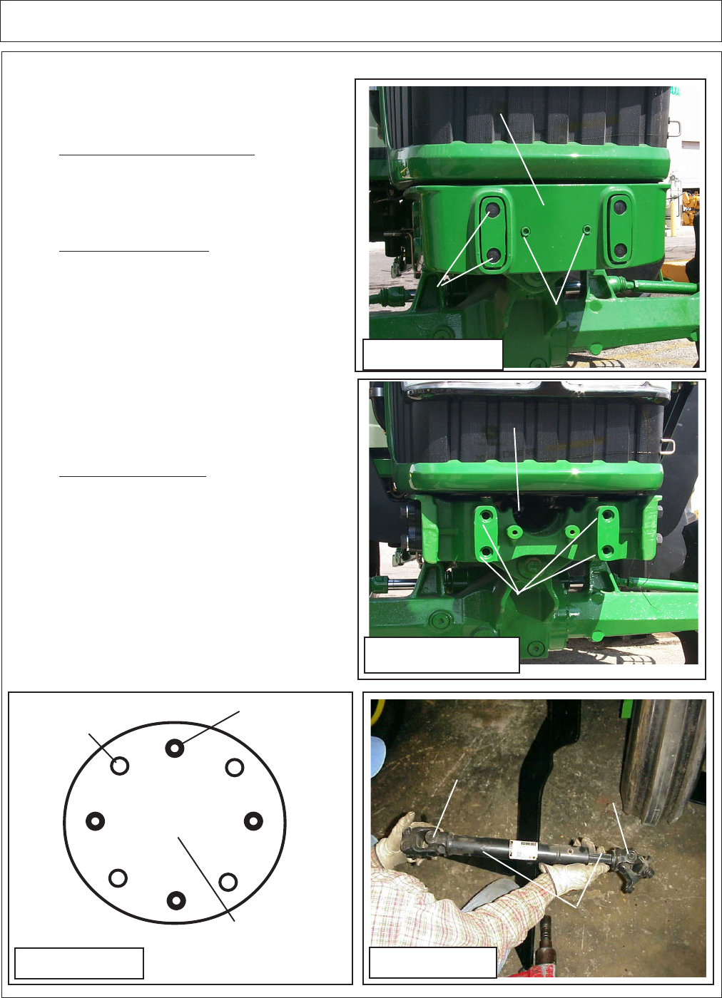
4. Driveshaft Assembly. The drive shaft is a
two piece Assembly, an inner and outer shaft
assembly (See Figure 5). The Shaft End has a
four bolt flange yokes on it that connect to the
Crankshaft Pulley Adapter. The Tube end has a
splined clamp yoke on it that connects to the
Pump. This Drive Shaft connects to the Pulley
Adapter. Note that the Universals of the Driveshaft
are in time. When installed in tractor they should be
in time as shown, both Yokes the same.
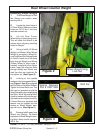
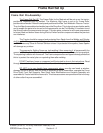
Front Cover Removed
Pump Plate Mounting Holes
Figure 3
Front Cover
Figure 2
Plastic Plugs
Cover
Retaining
Bolts (2)
4 Threaded
Holes
4
Non-Threaded
Holes
Pulley Adapter
Part # 02979790
Figure 4
Splined Clamp Yoke
/ Tube End
Flange Yoke
/ Shaft End
Drive Shaft
Assembly
Figure 5