


A-Boom (JD 6615 / 7615 Asy Instruction Manual) 07/03
© 2003 Alamo Group Inc.
Section 4 - 8
Frame Rail Installation
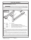
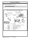
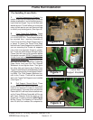
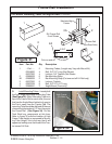
1. Lay Out Components in Display. It is
helpful to lay out the component in as neat a
display as possible. Lay out the Bolts accord-
ing to size and length. Lay out the Nuts and
washer by size. This will allow you to see how
many of each part as you use them and help
to identify any missing parts. (See figure 6)
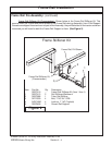
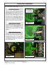
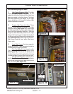
2. Front Frame Rail Supports. These
Frame Rail Support Mounts (part # 02979765
LH & 02979766 RH). These should already
be mounted from previous Assembly of
Front Pump and Drive Shaft Components. It
is easier to mount the Pump Drive Shaft
before these Frame Supports are installed. If
you are mounting the Frame rail supports
now, there are important things to remem-
ber. There are 4 bolts that go through Tractor
Frame that will have to be removed before
this can be mounted,
DO NOT remove these
4 bolts from both sides (LH & RH) of the
Tractor at the same time. Remove the 4 from
one side or the other, install the 4 retaining
(New Bolts) that hold the Rail Support
Weldment on and tighten them. Then go to
the other side and remove the 4 Bolts from
Tractor Frame Rail and install Machete Frame
rail Supports using the 4 new Support Retain-
ing Bolts. The Tank Support brackets con-
nect to the Tractor. These will be mounted
when the Frame Rail Supports are installed
(See Figure 7).
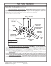
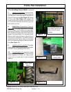
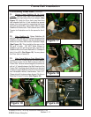
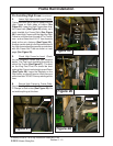
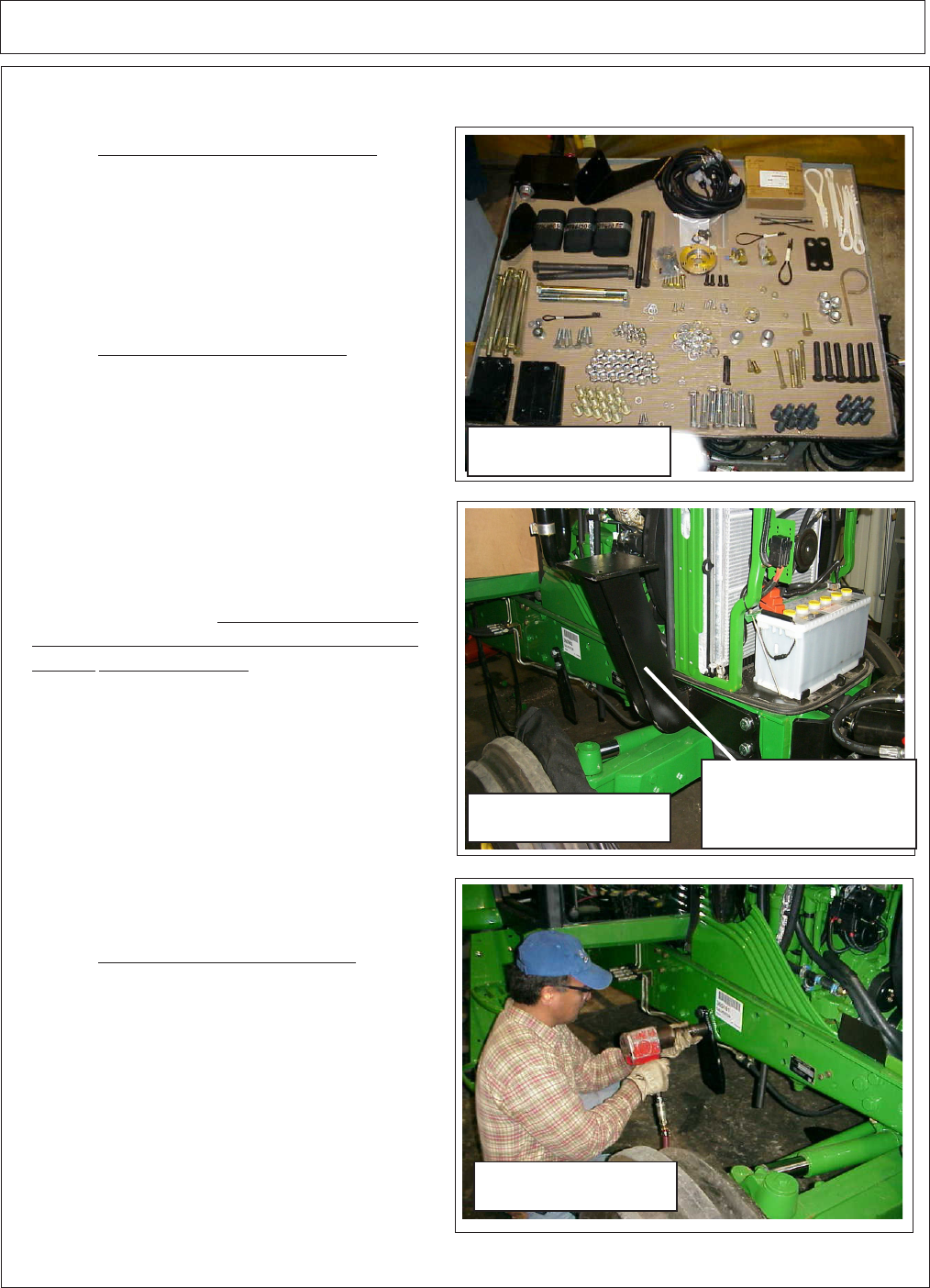
3. Rail Support Gusset Mount. There
are two Bolts in the Tractor frame rail that will
need to be removed in order to mount this
gusset support. It is easier to do now with the
frame rails off. It will need to be installed now,
as the Frame Stiffener Assembly will line up
with these Gussets. Note the angle on the
Gusset as it is being mounted (See Figure
8) See Figure 2 for drawing of Frame Stiff-
ener Kit and Part numbers for components.
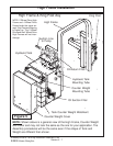
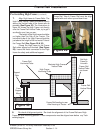
Pre-Installing Frame Rails:
Frame Rail
Support Brackets
Figure 7
Figure 6
Figure 8