


© 2003 Alamo Group Inc.
Section 4 - 23
A-Boom(JD 6615/ 7615 Asy Instruction Manual) 07/03
Frame Rail Installation
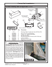
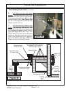
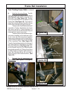
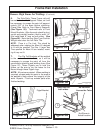
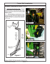
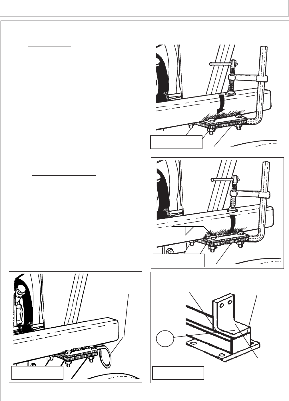
6. The Side Rails. These Frame rails will
be welded to the Rail Support Plates, so it will
be necessary to scrape the paint off approxi-
mately 5/8" of the base before attaching.
Clamp Side Rails to Front Mount Supports.
(See Figure 55). Tack-weld rails to Front
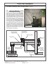
Mount Brackets. After thorough check for hori-
zontal and parallel location, weld a solid 1/4"
fillet weld bead 8" long on both sides. (See
Figure 56). Note that any Step Type Counter
Weight must clear the Left Rear Tire.
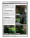
NOTE: There is a Tire Limit, This should be
addressed when ordering the Mount Kit designed
to fit with the specified Tire Size. If larger than
Tires specified for Mount Kit are installed, mount-
ing kit may not fit.
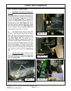
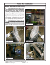
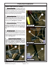
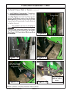
7. The Pig Tail Brackets will be welded
to the underside of the Rails, so it will be
necessary to scrape the paint off from this
area before attaching and welding them (See
Figure 57). These Pigtails are to hold the
Hoses up. Be sure to run the hoses for the
Boom through these Pigtail rings.
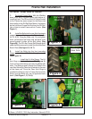
NOTE: All parts are painted. When welding is
required, scrape away the paint in the area to
be welded to help assure the integrity of the
weld. Repaint / Touch-up welded parts after
finished welding.
Remove High Frame for Welding.: (Continued)
1/4"
Figure 56
Figure 55
Weld here on
both sides.
Do not weld
Across the Tube.
Figure 57
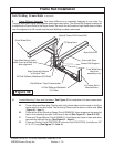
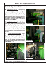
Figure 58
Pigtail Bracket
3
Not Shown in
Actual Location