


A-Boom (JD 6615 / 7615 Asy Instruction Manual) 07/03
© 2003 Alamo Group Inc.
Section 9 - 10
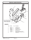
Wire Harness / Valve Mounting 2 WD & 4 WD
Installing Wire Harness
To Valve:
(Continued)
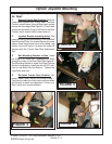
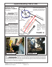
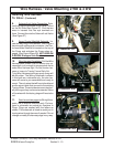
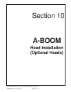
8. Solenoid Lock Valve Connection. Sole-
noid Lock valve is mounted on the Valve Tilt Port
on the RH Side (See Figure 27). Find the two
wires in harness that has eye terminals on
them. Connect them to the Solenoid Lock Valve
(See Figure 27)
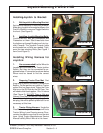
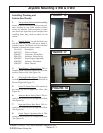
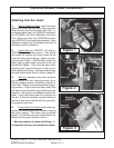
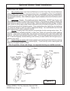
9. Servo Control Manifold Solenoid. Lo-
cate the last Plug in the harness. This Plug is a
two wire self sealing push connector. the Con-
trol manifolds Solenoid is located on the top of
the Pump and activates the Pump when en-
gaged. (See Figure 28 and 29).
NOT USED ON
A-BOOM, Disregard this Section
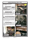
10. Wire Harness Completed. Pull the Wire
harness back toward Cab to remove any ex-
cess slack, only enough to remove slack not to
make Wire Harness tight. Do Not tie wire har-
ness or hoses to Tractor Frame Rails Yet.
Tying Wire Harness and Hose up out of way will
be done later. The Wiring Schematic is shown
in this book as a reference only, the wire har-
ness will come to you assembled and ready to
mount. The only wires that will have to be altered
are the wires inside that connect to the existing
Tractor Wires. These inside wires are intention-
ally left long so they can be cut as needed. None
of the wires with the factory plugs will have to be
cut.
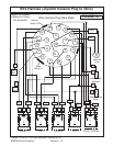
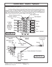
11. See the next two pages for Wiring Sche-
matic, this is listed as reference only. Pin loca-
tions in schematic are actual pin locations in
Plugs. Plugs are marked with the letters as
shown. This schematic is listed to assist you in
tracing wires through harness if needed. Do not
change or modify the harness plugs in any way.
FIGURE 27
Solenoid
Lock Valve
FIGURE 28
FIGURE 29
Servo Control
Manifold Solenoid
Servo Control
Manifold Solenoid
Plug