


© 2003 Alamo Group Inc.
A-Boom (JD 6615 / 7615 Asy Instruction Manual) 07/03
Section 8 - 5
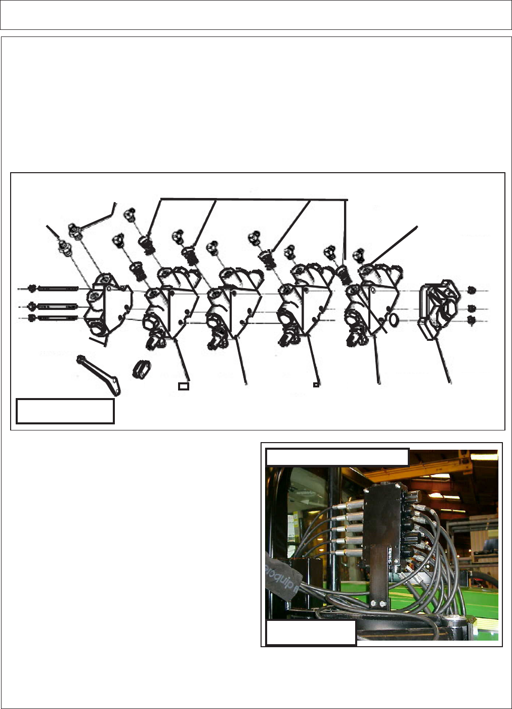
Cylinder Control Valve Installation
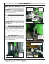
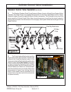
Figure 6
5 Spool Valve Shown
Pressure
Return
One Way Restrictors
"B' Side
Ports
End Cap
"A" Side
Ports
Tilt
Dipper
Lift
Swing
Handle
Inlet Cover
Figure 5
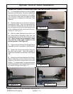
Standard Control Valve Operation:(continued)
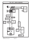
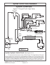
2. The Standard Tandem (Dual) Pump System is Shown, there is a Single Pump System Option
available. The Single Pump only supplies the Hydraulics for the Cutter Head Motor and the Tractor
Hydraulic System is used to supply the Boom Cylinder movements. The Schematic is very much the
same except the Cylinder Control Valve Hose connections are run to and from the tractor instead of
the way they are shown in the Schematic on the next page. (See System Schematic drawings for Pump
Repair Section)
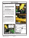
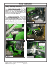
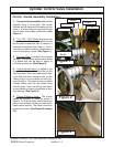
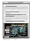
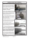
3. The Control valve will bolt on the top of the
High Frame on the right hand side. There is a tab
welded to the Frame that has two holes in it, the
Valve mount plate will bolt to this tab and the valve
will bolt to mount plate (See Figure 6) The Valve
in Figure 6 shows the Hoses and Control Cables
already connected, this is for illustration only. The
Control Cables and Hoses are connected after
the Valve is bolted to the mount plate. Most of the
Hoses shown in figure 6 are running from the
Boom. These Hoses must be connected to the
correct Port on the valve and to the correct side
to operate correctly.