


© 2003 Alamo Group Inc.
A-Boom (JD 6615 / 7615 Asy Instruction Manual) 07/03
Section 8 - 11
Cylinder Control Valve Installation
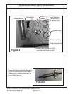
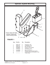
10. Each cable is controlled by the operator with
the use of single axis control handle assemblies. A
single control handle assembly is required to oper-
ate each individual valve section. The control
handle assemblies are ordered as PN 02971243
Control Assembly - Controller End -
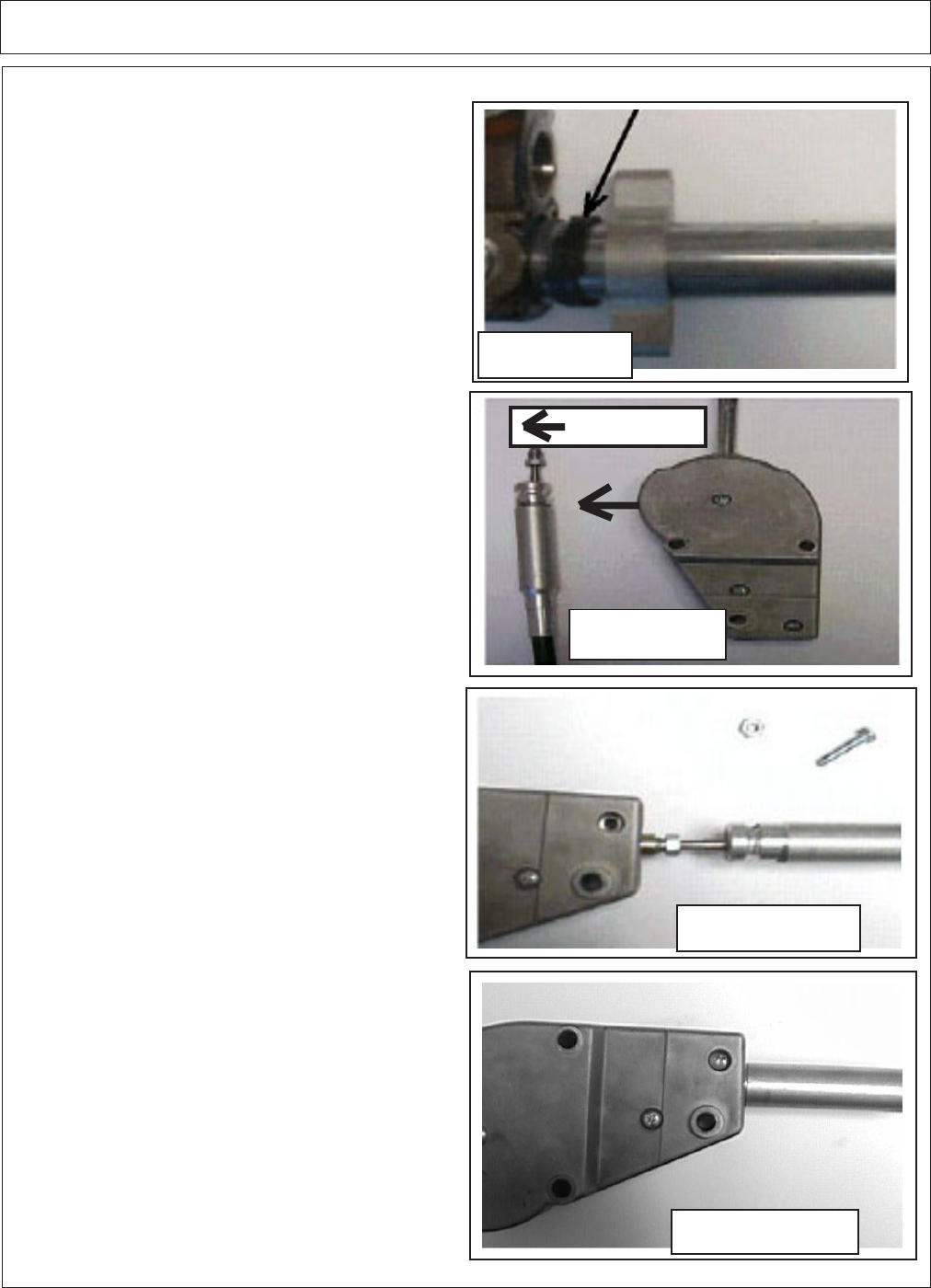
Installation Procedure:
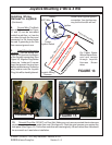
1. Each controller assembly comes fully as-
sembled. All required hardware etc. is included.
The control cables are not included with the control
handles and should be ordered separately. The
Controller must face forward as shown or controls
will be backward (See Figure 12)
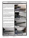
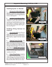
2. To attach the cable, manipulate the controller
handle so that the attachment nut is exposed as
shown. Remove the lower most nut and screw
from the controller housing.
Thread the cable nut into the controller attachment
nut and tighten. (See Figure 13)
3. Allow the controller handle to return to neutral.
Slide the cable guide tube into the control housing
and reinstall and tighten the housing screw.
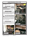
4. Check the operation of the spool,
cable and controller. Some adjustment at the valve
end may be required too ensure that the spool
returns to neutral when the controller is in the
neutral position. (See Figure 14)
5. The control lever assemblies utilizes a small
spring to make up for free play in the cable to valve
connection. The control valve spool spring pro-
vides the centering capabilities of the controller
and the valve spool. Lack of centering at the
controller is normally attributed to poor ad-
justment at the valve to cable connection or
binding of the cables due to poor routing.
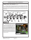
6. The control lever assemblies will bolt to-
gether to form a group of handles, there will be 4 for
thr 4 spool valve and 5 for the 5 spool valve. Also
the "ON" and "OFF" Switch will bolt to the Handles
(See Figure 15)
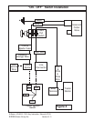
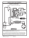
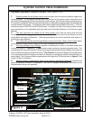
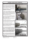
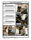
REMOTE CABLE OPERATION AND INSTALLATION: (continued)
Figure 11
Figure 12
Figure 13
Figure 14
Tractor Front