


© 2003 Alamo Group Inc.
A-Boom (JD 6615 / 7615 Asy Instruction Manual) 07/03
Section 8 - 7
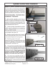
Cylinder Control Valve Installation
A
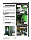
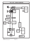
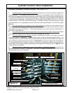
Cylinder Hydraulic Control Circuit: (See Figure 2 & 3)
1. Hydraulic power for the cylinder control circuit is taken from the second (smaller) stage of the
hydraulic pump. Oil is supplied through hose 2 to the four (or five) spool control valve where it is
directed to the appropriate cylinder through the cylinder hoses. All of the cylinders are double acting.
The system is protected from excessive pressure by an adjustable pressure relief valve located on
the inlet section of the valve. The pressure relief valve is factory set at 2000 PSI for the 17, 20, & 23
foot booms and to 2500 PSI on the 28 foot booms. In addition, at least 3 individual cylinder circuits
are protected by a non-adjustable work port relief valve (See Specifications in the Service repair
Manual).
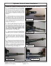
2. One way restrictors are added to the valve sections such that the return flow from the
cylinders when performing gravity aided function will slow the flow of return oil and allow for a more
controllable movement of the boom. (See the specifications for size of restriction and location in
the Service repair Manual).
3. Oil is returned from the valve through Return hose to the Cutter / Motor Control valve where
it then passes through Return hose into the return filter and into the tank.
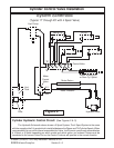
4. The valve utilized on the A-Boom mowers to facilitate the control of the boom movement
functions is either a
* 4 Spool or * 5 Spool, open center, sectional, manually operated valve. The
manual operation is performed with the use of normal directly attached valve handles or through the
use of cables and remote mechanical levers.
* The 5 Spool has one more Spool than shown below,
it is to operate the Boom Extension on the 28 ft; Boom or to operate a hydraulic activated Door on
some heads. The 5 th spool will be located between the Dipper and Tilt Spool shown in figure 3. (See
Figure 15 later in this book)
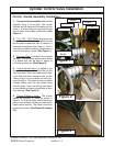
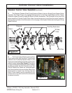
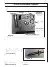
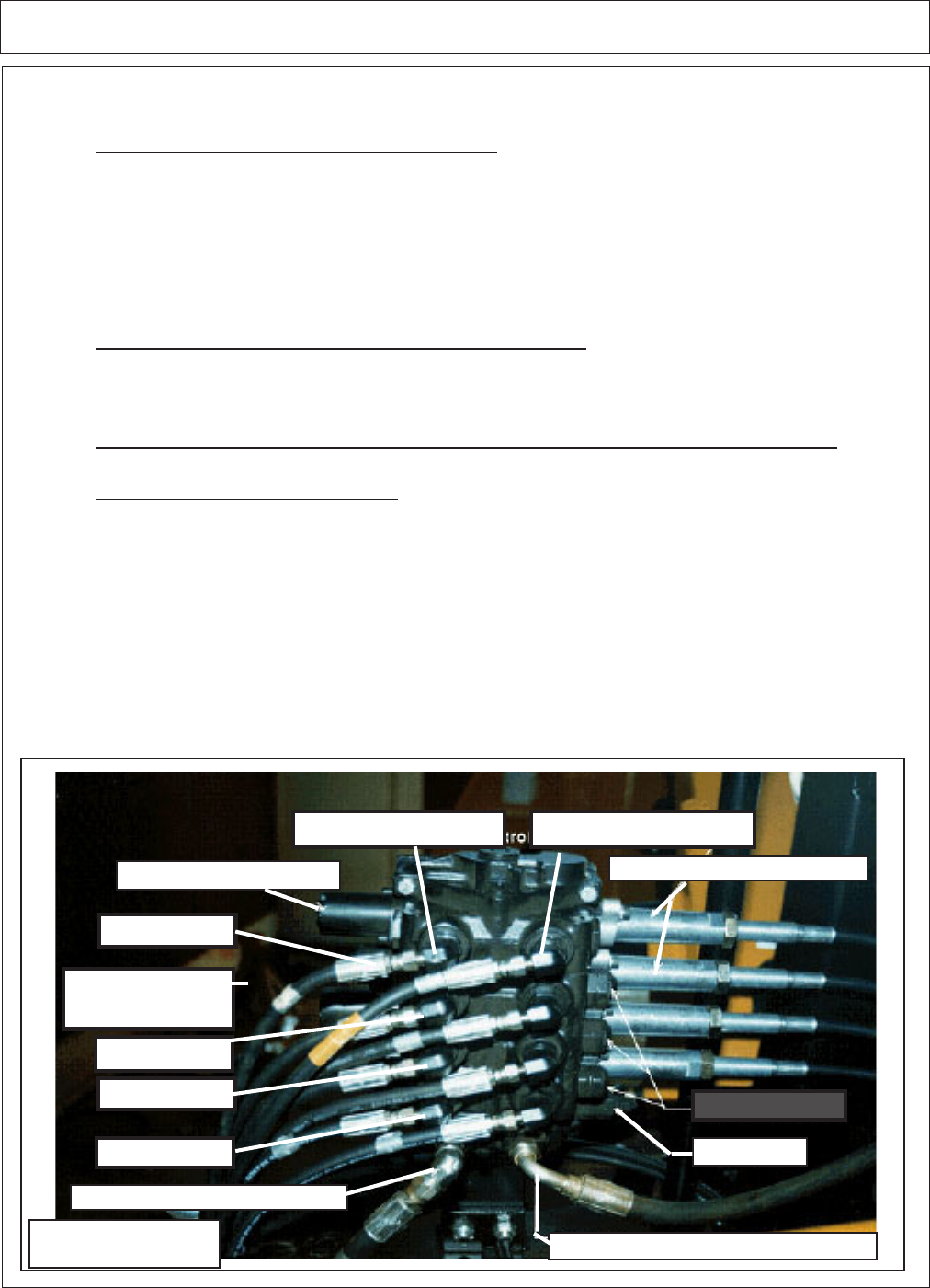
5. Although similar in appearance, each valve section is specifically designed to perform the
specified function for which it is assigned. The Valve is shipped assembled and should not be
disassembled during unit assembly.
Spool Detent Assembly
Control Cable Attachment
Main Relief
Pressure from Pump
Return to Cutter/Motor Valve
"A" Port Side"B" Port Side
Swing
Lift
Dipper
Tilt
Figure 3
* Boom Extend
or Door
?
Swing
Lift
Dipper
Tilt