


© 2003 Alamo Group Inc.
Section 4 - 3
A-Boom(JD 6615/ 7615 Asy Instruction Manual) 07/03
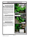
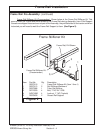
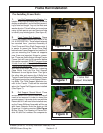
Frame Rail Installation
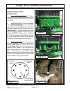
RH & LH Frame Rails. Shown below are example of Frame rails, There is a Right and Left Frame
Rail, They will not interchange from side to side. LH must be mounted on the Left and Right on the Right.
To ID which is which, the easiest way is to look for the Counter Weight Mounting Tubes (See Figure
1 Item 2), these are welded on to the LH Frame Rail Only. The Rail Mounting Pad (See Figure 1 Item
4) is loose and not welded to the front of the Frame Rail untill final assembly.
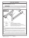
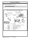
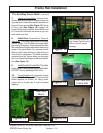
Frame Rail Pre-Assembly: (continued)
Note:
Item 3 is welded to both LH and RH Frame Rails from the factory. Item 4 will be welded on
during assembly procedures. Do not weld on any components until instructed to do so, then check
instructions carefully because some components are only to be tack welded then removed to be
welded later.
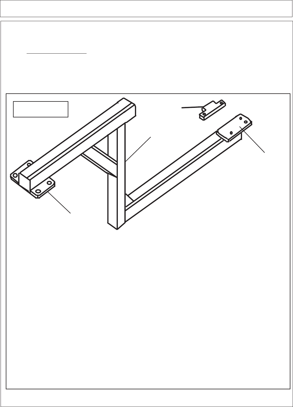
Actual Tube Design may vary from drawing above. Shown above is a general Frame
Rail Weldment. While Frame Rails may be designed different the mounting process will be the
same.
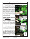
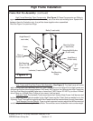
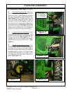
3 Point Arm Stabilizers on tractor will have to be removed when mounting Frame rails
and will have to be modified to be used again. This modification will be customers responsibility.
Item Part No. Qty Description
1 02979767 1 4 WD Frame Rail Weldment, LH (Shown)
02979768 1 4 WD Frame Rail Weldment, RH (Not Shown)
3 ------------- 2 Rear Mounting Plate (Welded on LH and RH Frame Rail)
4 02725900 2 Front Rail Mounting Pad (not welded to frame rail when recievedl)
5 02974704 2 Stabilizer Strap, (Axle Straps) Fit above Axle.
Figure 1
1
3
4
5