Workman MDX--D
Electrical System
Page 5 -- 1 6
Glow Plug Controller
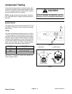
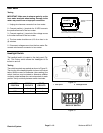
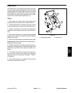
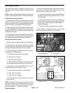
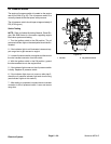
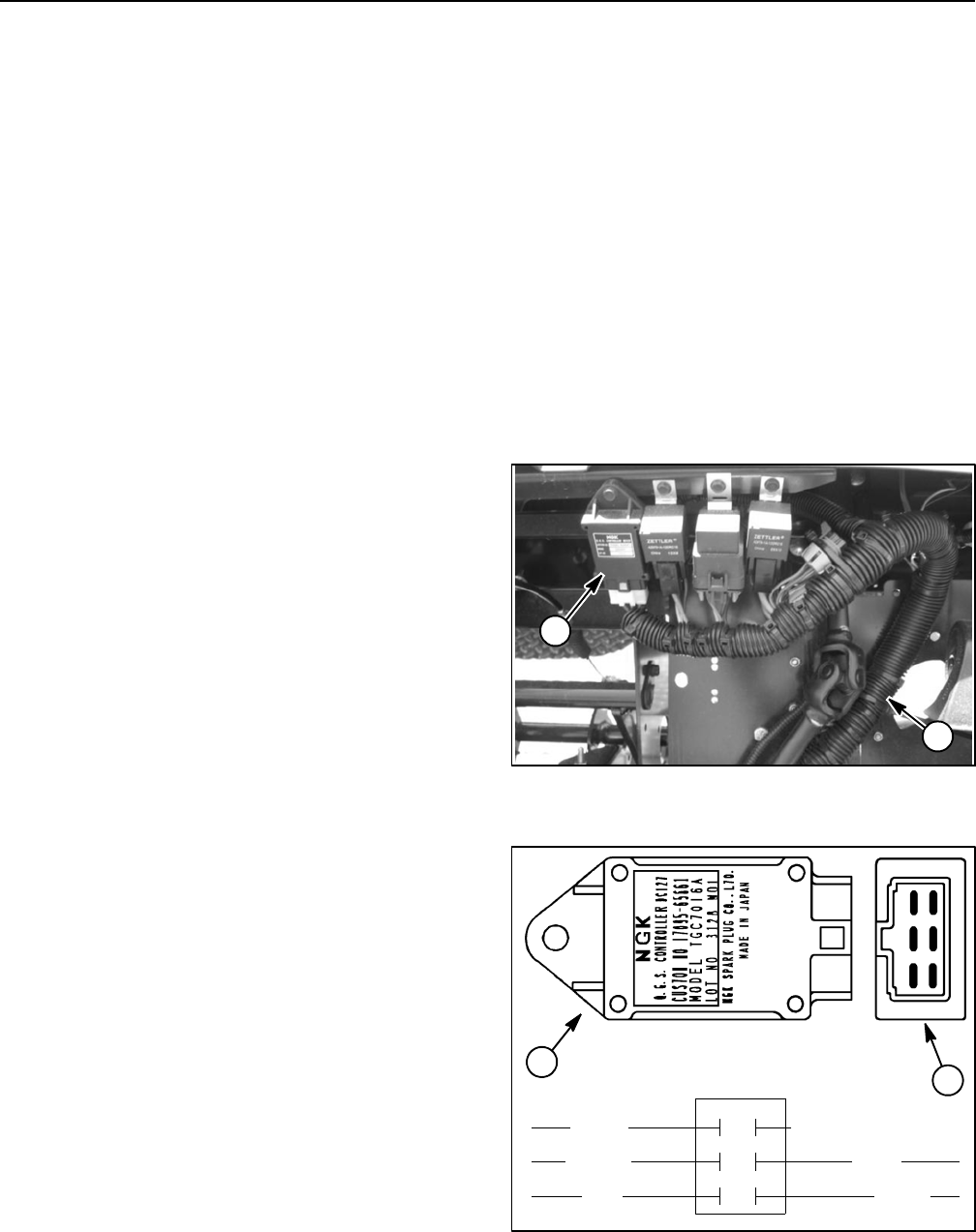
The glow plug controller is attached to the front of the
dash bracket and can be accessed by raising the hood
(Fig. 21).
NOTE: When troubleshooting the glow controller, refer
to electrical drawings in Chapter 7 -- Electrical Drawings.
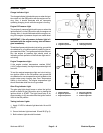
Glow Plug Controller Operation
1. When the ignition switch is initially placed in the ON
position, the glow plug controller energizes the glow
plugs for six (6) seconds. The console glow plug indica-
tor light will also be illuminated for six (6) seconds.
2. When theignition switchis turned tothe START posi-
tion, the glow plugs will energize as long as the switch
is held in START. The console glow plug indicator light
will not be illuminated.
3. When the ignition switch is released from the START
to the O N position, the glow plugs will de--energize and
the console glow plug indicator light will remain off.
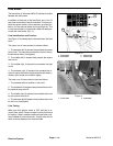
Glow Plug Controller Checks
1. Make sure there is electrical power from the battery.
2. Disconnect the wire harness electrical connector
from the engine run solenoid to prevent the engine from
starting (see Engine Run Solenoid in this section).
3. Place ignition switchin theON position. Verify thefol-
lowing while in the ON position:
A. Glow plug indicator light is illuminated.
B. Glow relay is energized.
C. Glow plugs are energized.
D. Glow plug indicator light goes out and glow p lugs
de--energize after approximately six (6) seconds.
4. PlaceignitionswitchintheSTARTposition.Verify
thefollowingwhileintheSTARTposition:
A. Glow plug indicator light is not illuminated.
B. Glow relay is energized.
C. Glow plugs are energized.
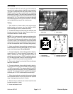
D. Electrical power exists at terminal 1 of the glow
plug controller.
NOTE: If there is no electrical power at terminal 1 of the
glow plug controller, verify continuity ofthe circuitry from
the ignition switch to the controller and perform Step 4
again (see Chapter 7 -- Electrical Drawings).
5. If any of the conditions inStep3 are notmet orelectri-
cal power to controller terminal 1 exists and any of the
other conditions in Step 4 are not met:
A. Verify continuity ofthe circuitry fromthe battery to
the glow relay and glow plugs (see Chapter 7 -- Elec-
trical Drawings).
B. Verify continuity ofthe circuitry fromthe battery to
ignition switch,glow plugcontroller, glow plugindica-
tor light, glow relay and ground (see Chapter 7 --
Electrical Drawings).
C. Repair or replace components a s necessary.
6. After testing is completed, connect wire harness
electrical connector to the engine run solenoid.
1. Glow plug controller 2. Wire harness
Figure 21
2
1
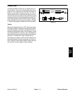
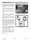
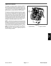
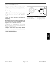
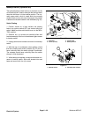
1. Controller top view 2. Controller end view
Figure 22
3
2
1
6
4
5
1
2
TEMP (not used)
GLOW
GROUND
VIOLET
+12V
LAMP
START
GRAY
BLACK
PINK
ORANGE
CONTROLLER
1
2
3
4
5
6
CONNECTIONS


