Workman MDX--DPage 3 -- 18Diesel Engine
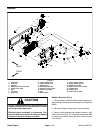
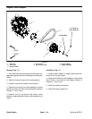
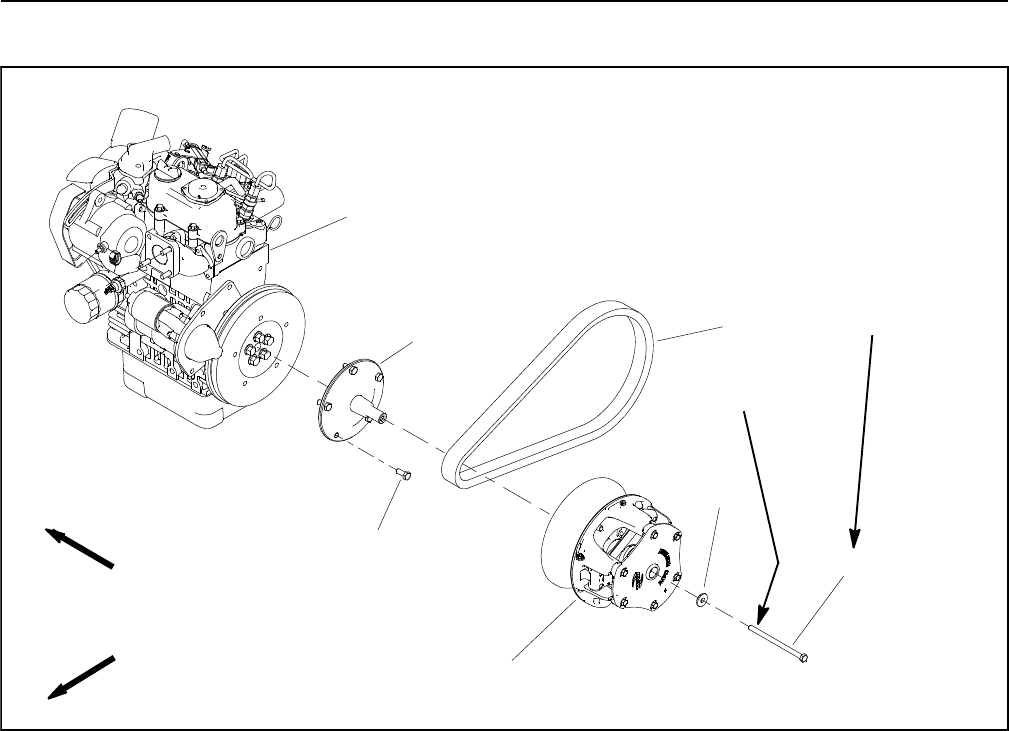
Engine Clutch Adapter
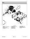
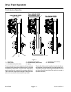
Figure 17
1. Drive belt
2. Cap screw
3. Flange washer
4. Drive clutch
5. Cap screw (5 used)
6. Clutch adapter
7. Engine assembly
2
5
6
4
7
3
1
FRONT
RIGHT
17 to 22 ft--lb
(23to29N--m)
Loctite #242
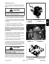
Removal (Fig. 17)
1. Park machine on alevel surface, stopthe engine, en-
gage parking brake and remove thekey fromthe ignition
switch.
2. Raise and support cargo bed to access engine.
3. Carefully remove drive belt from drive clutch.
4. Remove drive clutch from clutch adapter on engine
(see Drive Clutch in the Service and Repairs section of
Chapter 4 -- Drive Train).
5. Remove five (5) cap screws that secure clutch
adapter toengine flywheel. Remove clutch adapter from
engine.
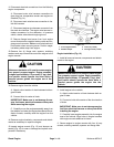
Installation (Fig. 17)
1. Position clutch adapter to engine flywheel and se -
cure with five (5) cap screws.
2. Secure drive clutch to clutch adapter on engine (see
Drive Clutch in the Service and Repairs section of
Chapter 4 -- Drive Train).
3. Install drive belt to drive clutch.
4. Lower and secure cargo bed.


