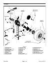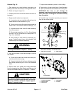
Workman MDX--DPage 4 -- 12Drive Train
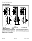
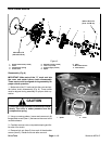
Drive Clutch Service
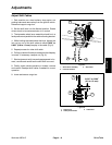
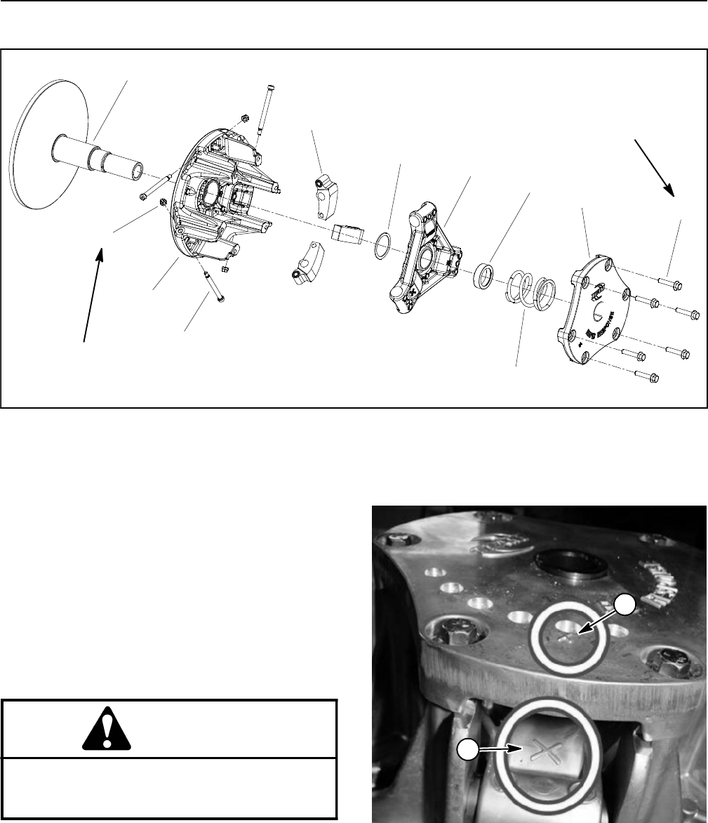
Figure 8
v
105 to 120 in--lb
(12to13.5N--m)
40 to 50 in--lb
(4.6 to 5.6 N--m)
1. Flange head screw (6 used)
2. Cover
3. Compression spring
4. Limiter shim
5. Shoulder screw (3 used)
6. Lock nut (3 used)
7. Clutch weight (3 used)
8. Spider
9. Shim
10. Moveable sheave
11. Fixed sheave
2
3
6
8
9
10
1
5
7
4
11
Disassembly (Fig. 8)
IMPORTANT: Make note of the “X” mark cast into
the cover and spider before clutch disassembly.
These marks must be aligned during assembly for
proper clutch operation.
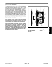
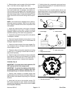
1. Make noteof the“X” mark castinto the coverand spi-
der before clutch disassembly (Fig. 9). These marks
must be aligned during assembly for proper clutch op-
eration.
CAUTION
Loosen the flange head screws that secure cover
slowly. The cover is under pressure from the
compression spring.
2. Using a crossing pattern, loosen and remove six (6)
flange head screws (item 1) that secure the cover to the
movable sheave.
3. Carefully remove cover, compression spring andlim-
iter shim from clutch.
4. Remove lock nut (item 6) from each of the shoulder
screws (item 5). Discard lock nuts after removal.
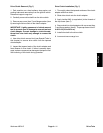
1. Spider 2. Cover
Figure 9
2
1


