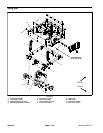
Workman MDX--DPage 6 -- 20Chassis
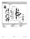
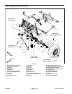
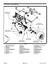
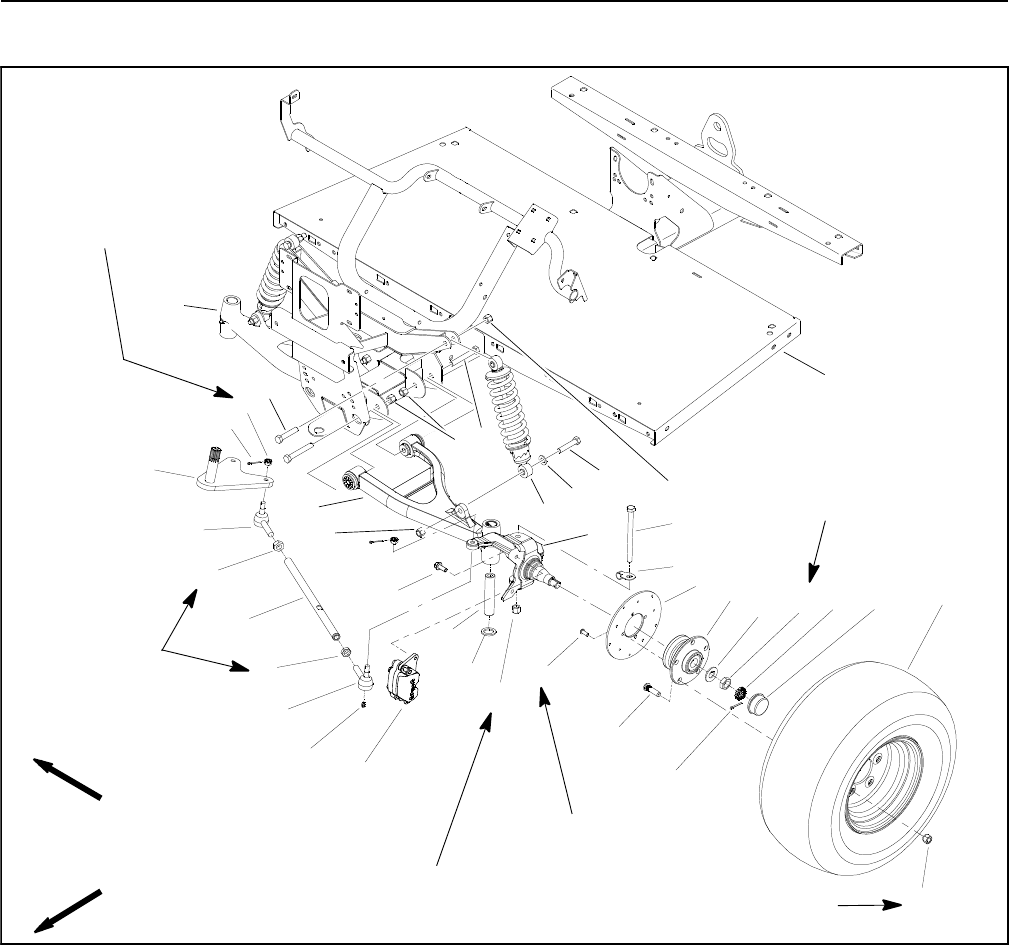
A--arms and Front Suspension
Figure 15
FRONT
RIGHT
6
19
2
5
7
6
14
7
8
12
4
16
11
18
3
17
1
15
23
22
9
10
13
20
21
24
25
26
27
28
29
30
31
80 to 90 ft--lb
(109 to 122 N--m)
20 to 25 ft--lb
(28 to 33 N--m)
45 to 55 ft--lb
(62 to 74 N--m)
See text for
tightening procedure
6
1. Steering gearbox pitman arm
2. Shock absorber (2 used)
3. Cotter pin
4. Slotted hex nut
5. Flat washer
6. Lock nut (3 used per side)
7. Cap screw (2 used per shock)
8. LH A--arm
9. Brake rotor
10. Wheel hub assembly
11. Tab washer
12. RH A--arm
13. Jam nut
14. Front frame
15. Nut retainer
16. Dust cap
17. Wheel assembly
18. Lug nut (5 used per wheel)
19. Cap screw (2 used per A--arm)
20. Cotter pin
21. Wheel stud (5 used per hub)
22. Socket screw (4 used per rotor)
23. Brake caliper (LH shown)
24. Lock nut
25. Flange screw (2 used per caliper)
26. Grease fitting
27. Ball joint (LH threads)
28. Jam nut (LH threads
29. Tie rod
30. Jam nut (RH threads)
31. Ball joint (RH threads)
32. Kingpin sleeve
33. Thrust washer
34. Spindle (LH shown)
35. Brake hose clip
36. Cap screw
32
33
34
35
36
75 to 100 ft--lb
(102 to 135 N--m)
9 to 11 ft--lb
(13to14N--m)


