


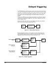
Delayed Triggering
Reference
3Ć24
7. Press Source (main) ➞ Ch1, Ch2, Ch3 (Ax1 on the TDS 620A), Ch4
(Ax2 on the TDS 620A), or Auxiliary (side).
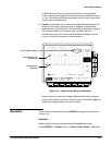
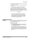
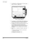
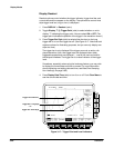
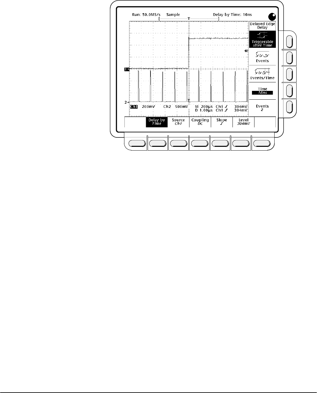
Figure 3Ć15:ăDelayed Trigger Menu
8. Press Coupling (main) ➞ DC, AC, HF Rej, LF Rej, or Noise Rej (side)
to define how the input signal will be coupled to the delayed trigger. For
descriptions of these coupling types, see Triggering on page 2Ć13.
9. Press Slope (main) to select the slope that the delayed trigger will occur
on. Choose between the rising edge and falling edge slopes.
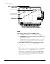
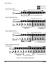
When using Delayed Triggerable mode to acquire waveforms, two
trigger bars are displayed. One trigger bar indicates the level set by the
main trigger system; the other indicates the level set by the delayed
trigger system.
10. Press Level (main) ➞ Level, Set to TTL, Set to ECL,orSet to 50%
(side).
H Level lets you enter the delayed trigger level using the general
purpose knob or the keypad.
H Set to TTL fixes the trigger level at +1.4ĂV.
H Set to ECL fixes the trigger level at -1.3ĂV.