


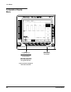

Triggering
Operating Basics
2Ć16
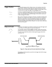
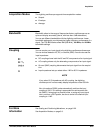
Holdoff Holdoff
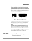
Trigger Points
Trigger Level
Holdoff
Acquisition
Interval
Acquisition
Interval
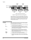
Triggers are Not Recognized During Holdoff Time
Figure 2Ć2:ăTrigger Holdoff Time Ensures Valid Triggering
Holdoff is settable from 0% (minimum holdoff available) to 100% (maximum
available). To see how to set holdoff, see Mode & Holdoff on page 3Ć35. The
minimum and maximum holdoff varies with the horizontal scale. See Holdoff,
Variable, Main Trigger in the TDS 620A, 640A, & 644A Performance VerificaĆ
tion Manual, Section 2 on Specification, Typical Characteristics for typical
minimum and maximum values.
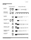
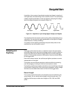
Trigger coupling determines what part of the signal is passed to the trigger
circuit. Available coupling types include AC, DC, Low Frequency Rejection,
High Frequency Rejection, and Noise Rejection:
H DC coupling passes all of the input signal. In other words, it passes both
AC and DC components to the trigger circuit.
H AC coupling passes only the alternating components of an input signal.
(AC components above 10 Hz are passed if the source channel is in
1 MW coupling; above 200 kHz are passed in 50 W coupling.) It removes
the DC components from the trigger signal.
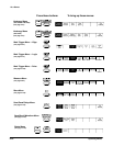
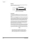
H High frequency rejection removes the high frequency portion of the
triggering signal. That allows only the low frequency components to
pass on to the triggering system to start an acquisition. High frequency
rejection attenuates signals above 30 kHz.
H Low frequency rejection does the opposite of high frequency rejection.
Low frequency rejection attenuates signals below 80 kHz.
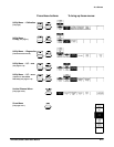
H Noise Rejection lowers trigger sensitivity. It requires additional signal
amplitude for stable triggering, reducing the chance of falsely triggering
on noise.
Coupling