


Logic Triggering
TDS 620A, 640A & 644A User Manual
3Ć77
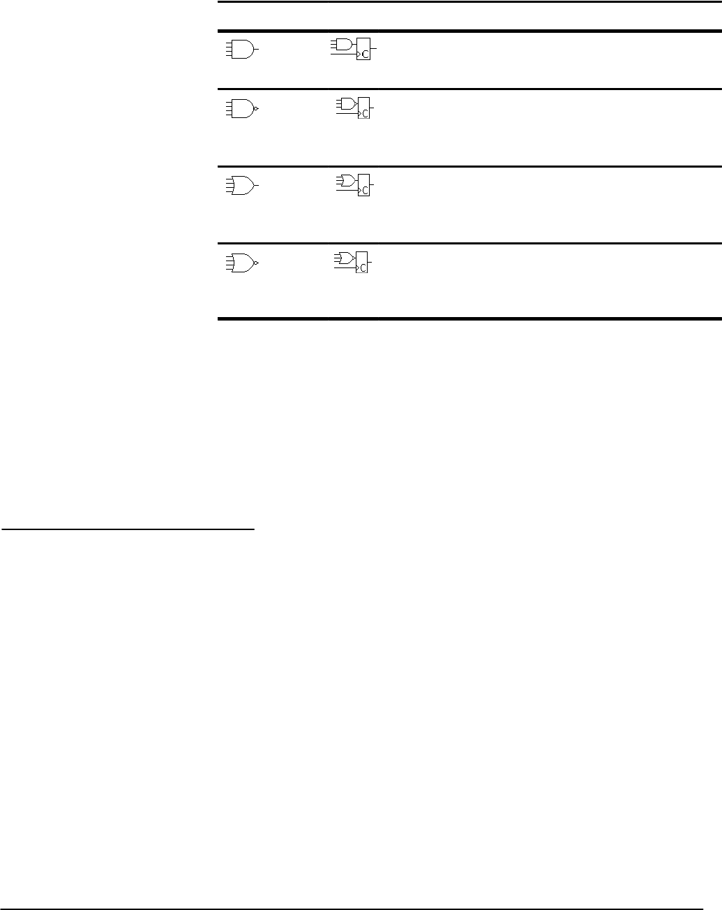
TableĂ3Ć3:ăLogic Triggers
Pattern
State Definition
1,2
AND Clocked AND If all the preconditions selected
for the logic inputs
3
are true,
then the oscilloscope triggers.
NAND Clocked NAND If not all of the preconditions seĆ
lected for the logic inputs
3
are
true, then the oscilloscope trigĆ
gers.
OR Clocked OR If any of the preconditions seĆ
lected for the logic inputs
3
are
true, then the oscilloscope trigĆ
gers.
NOR Clocked NOR If none of the preconditions seĆ
lected for the logic inputs
3
are
true, then the oscilloscope trigĆ
gers.
1
Note that for State class triggers, the definition must be met at the time the clock input
changes state. See the descriptions for Pattern and State in this section.
2
The definitions given here are correct for the Goes True setting in the Trigger When menu.
If that menu is set to Goes False, swap the definition for AND with that for NAND and for OR
with NOR for both pattern and state classes.
3
The logic inputs are channels 1, 2, 3, and 4 for the TDS 640A & TDS 644A and 1, 2, Aux 1
and Aux 2 for the TDS 620A when using Pattern Logic Triggers. For State Logic Triggers,
channel 4 (Aux 2 for the TDS 620A) becomes the clock input, leaving the remaining chanĆ
nels as logic inputs.
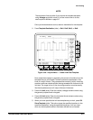
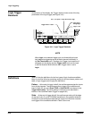
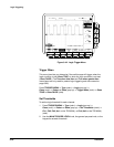
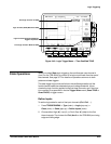
The Logic Trigger menu (Figure 3Ć42) lets you select when to trigger (true or
false), set the thresholds for each channel, select the mode (auto or normal),
and adjust the holdoff.
Press TRIGGER MENU ➞ Type (main) ➞ Logic (popĆup) ➞
Class (main) ➞ Pattern or State (popĆup).
Operations Common
to Pattern and State