


Probe Selection
Reference
3Ć106
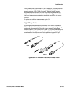
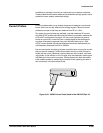
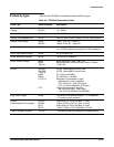
Optical probes let you blend the functions of an optical power meter with the
highĆspeed analog waveform analysis capability of an oscilloscope. You
have the capability of acquiring, displaying, and analyzing optical and elecĆ
trical signals simultaneously.
Applications include measuring the transient optical properties of lasers,
LEDs, electroĆoptic modulators, and flashlamps. You can also use these
probes in the development, manufacturing, and maintenance of fiber optic
control networks, local area networks (LANs), fiberĆbased systems based on
the FDDI and SONET standard, optical disk devices, and highĆspeed fiber
optic communications systems.
NOTE
When you connect any level 2 probe to the oscilloscope, the input
impedance of the oscilloscope automatically becomes 50 W.Ifyou
then connect a high input impedance passive probe you need to
set the input impedance back to 1ĂMW. Vertical Control, on page
3Ć136, explains how to change the input impedance.
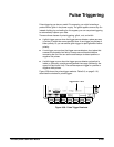
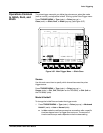
The instantaneous timeĆinterval to voltage converter (TVC) continuously
converts consecutive timing measurements to a timeĆinterval versus time
waveform.
Timing variations typically appear as leftĆtoĆright motion, or jitter, on an
oscilloscope. Time base or trigger holdoff adjustments may improve display
stability, but they do not show timing dynamics. The TVC untangles the
often confusing waveforms and delivers a coherent realĆtime view.
The TVC adds three measurement functions to the voltage versus time
capability of your oscilloscope: time delay versus time, pulseĆwidth versus
time, and period versus time.
Optical Probes
TimeĆtoĆVoltage
Converter