


TDS 620A, 640A & 644A User Manual
3Ć75
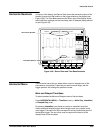
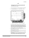
Logic Triggering
There are two classes of logic triggering: pattern and state.
A pattern trigger occurs when the logic inputs to the logic function you select
cause the function to become TRUE (or at your option FALSE). When you
use a pattern trigger, you define:
H The precondition for each logic input Ċ logic high, low, or do not care
(the logic inputs are channels 1, 2, 3, and 4 for the TDS 640A &
TDS 644A and 1, 2, Aux 1, and Aux 2 for the TDS 620A)
H The Boolean logic function Ċ select from AND, NAND, OR, and NOR
H The condition for triggering Ċ whether the trigger occurs when the
Boolean function becomes TRUE (logic high) or FALSE (logic low), and
whether the TRUE condition is time qualified (see page 3Ć80).
A state trigger occurs when the logic inputs to the logic function cause the
function to be TRUE (or at your option FALSE) at the time the clock input
changes state. When you use a state trigger, you define:
H The precondition for each logic input, channels 1, 2, and 3 for the
TDS 640A & TDS 644A (1, 2, and Ax1 on the TDS 620A)
H The direction of the state change for the clock input, channel 4 (Aux 2
for the TDS 620A)
H The Boolean logic function Ċ select from clocked AND, NAND, OR, and
NOR
H The condition for triggering Ċ whether the trigger occurs when the
Boolean function becomes TRUE (logic high) or FALSE (logic low)
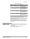
Table 3Ć3 on page 3Ć77 lists the preconditions required for each logic funcĆ
tion to issue a pattern or state logic trigger.