


Fast Fourier Transforms
Reference
3Ć44
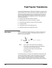
Where: DF is the frequency resolution.
Sample Rate is the sample rate of the source waveform.
FFT Length is the length of the FFT Time Domain waveform
record.
DF +
SampleĂ Rate
FFTĂ Length
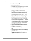
The sample rate also determines the range these frequencies span; they
span from 0 to ½ the sample rate of the waveform record. (The value of ½
the sample rate is often referred to as the Nyquist frequency or point.) For
example, a sample rate of 20 Megasamples per second would yield an FFT
with a range of 0 to 10 MHz. The sample rates available for acquiring data
records vary over a range the limits of which depend on your oscilloscope
model. TDS oscilloscopes display the sample rate in the acquisition readout
at the top of the oscilloscope screen.
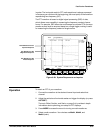
Offset, Position, and Scale
The following topics contain information to help you display your FFT propĆ
erly.
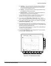
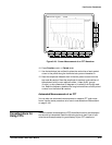
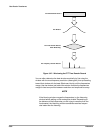
Adjust for a NonĆClipped Display Ċ To properly display your FFT waveĆ
form, scale the source waveform so it is not clipped.
H You should scale and position the source waveform so it is contained on
screen. (Off screen waveforms may be clipped, resulting in errors in the
FFT waveform).
Alternately, to get maximum vertical resolution, you can display source
waveforms with amplitudes up to two divisions greater than that of the
screen. If you do, turn on PkĆPk in the measurement menu and monitor
the source waveform for clipping.
H Use vertical position and vertical offset to position your source waveĆ
form. As long as the source waveform is not clipped, its vertical position
and vertical offset will not affect your FFT waveform except at DC. (DC
correction is discussed below.)
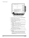
Adjust Offset and Position to Zero for DC Correction Ċ Normally, the
output of a standard FFT computation yields a DC value that is twice as
large as it should be with respect to the other frequencies. Also, the selecĆ
tion of window type introduces errors in the DC value of an FFT.
The displayed output of the FFT on TDS oscilloscopes is corrected for these
errors to show the true value for the DC component of the input signal. The
Position and Offset must be set to zero for the source waveform in the
Vertical menu. When measuring the amplitude at DC, remember that 1 VDC
equals 1 V
RMS
and the display is in dB.