Logic Triggering
TDS 620A, 640A & 644A User Manual
3Ć81
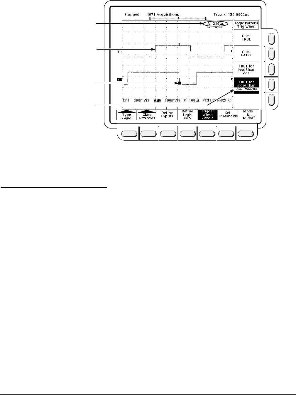
Logic Function (AND) Becomes TRUE
Logic Function Becomes FALSE and
Triggers Acquisition
Time Logic Function is TRUE
Time Logic Function Must be TRUE
Figure 3Ć43:ăLogic Trigger Menu Ċ Time Qualified TRUE
When you select State logic triggering, the oscilloscope uses channel 4
(Aux 2 on the TDS 620A) as a clock for a logic circuit made from the rest of
the channels. See page 3Ć77 for details on operations common to both
pattern and state triggers.
The state trigger logic works as follows: the oscilloscope waits until the
fourth channel meets the selected slope and voltage threshold. It then
checks the logic function applied to the first three channels, and if the funcĆ
tion condition is as specified in the the Trigger When menu (Goes TRUE or
Goes FALSE) a trigger occurs.
Define Inputs
To set the logic state for each of the input channels (Ch1, Ch2, ...):
1. Press TRIGGER MENU ➞ Type (main) ➞ Logic (popĆup) ➞
Class (main) ➞ State (popĆup) ➞ Define Inputs (main).
2. Choose either High (H), Low (L), or Don't Care (X) (side) for the first
three channels. The choices for Ch4 (Aux 2 on the TDS 620A) are rising
edge and falling edge.
State Operations


