Triggering
TDS 620A, 640A & 644A User Manual
2Ć17
The adjustable trigger position defines where on the waveform record the
trigger occurs. It lets you properly align and measure data within records.
The part of the record that occurs before the trigger is the pretrigger portion.
The part that occurs after the trigger is the posttrigger portion.
To help you visualize the trigger position setting, the top part of the display
has an icon indicating where the trigger occurs in the waveform record. You
select in the Horizontal menu what percentage of the waveform record will
contain pretrigger information.
Many users find displaying pretrigger information a valuable troubleshooting
technique. For example, if you are trying to find the cause of an unwanted
glitch in your test circuit, it may prove valuable to trigger on the glitch and
make the pretrigger period large enough to capture data before the glitch.
By analyzing what happened before the glitch, you may uncover clues about
the source of the glitch.
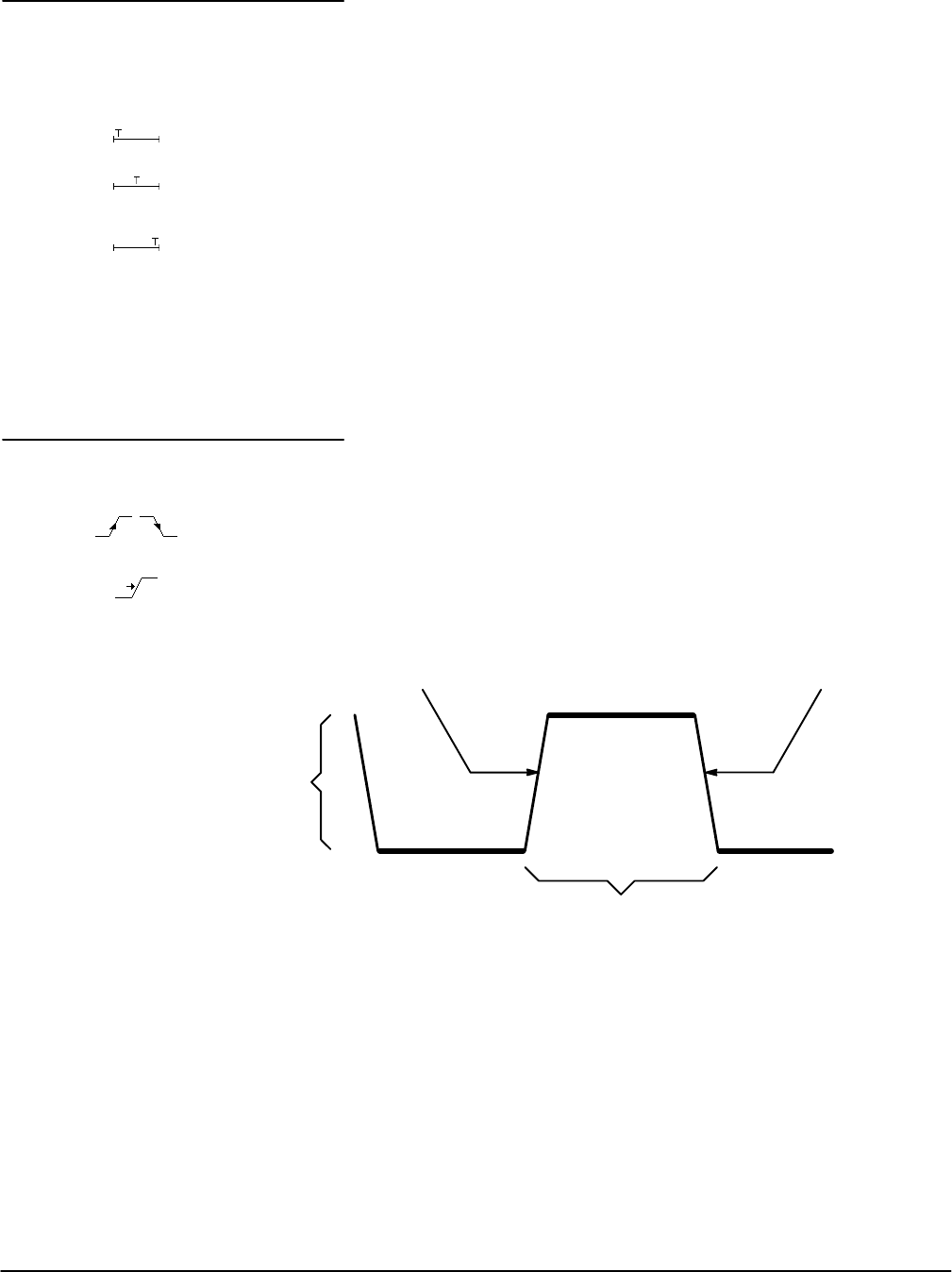
The slope control determines whether the oscilloscope finds the trigger point
on the rising or the falling edge of a signal (see Figure 2Ć3).
You set trigger slope by selecting Slope in the Main Trigger menu and then
selecting from the rising or falling slope icons in the side menu that appears.
The level control determines where on that edge the trigger point occurs
(see Figure 2Ć3).
PositiveĆGoing Edge NegativeĆGoing Edge
Trigger Slope Can be Positive or Negative
Trigger Level Can be
Adjusted Vertically
Figure 2Ć3:ăSlope and Level Controls Help Define the Trigger
The digitizing oscilloscope lets you set the main trigger level with the trigger
MAIN LEVEL knob.
Trigger Position
Slope and Level


