


Start Up
Getting Started
1Ć4
2. Leave space for cooling. Do this by verifying that the air intake and
exhaust holes on the sides of the cabinet (where the fan operates) are
free of any airflow obstructions. Leave at least 5.1 cm (2 inches) free on
each side.
WARNING
To avoid electrical shock, be sure that the power cord is disconĆ
nected before checking the fuse.
3. Check the fuse to be sure it is the proper type and rating (see FigĆ
ure 1Ć1). You can use either of two fuses. Each fuse requires its own cap
(see Table 1Ć1). The digitizing oscilloscope is shipped with the UL apĆ
proved fuse installed.
4. Check that you have the proper electrical connections. The digitizing
oscilloscope requires 90 to 250 VAC
RMS
, continuous range, 47 Hz to
63 Hz, and may require up to 300ĂW.
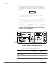
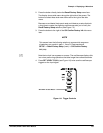
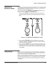
5. Connect the proper power cord from the rearĆpanel power connector
(see Figure 1Ć1) to the power system.
Power Connector
Principal Power Switch
Fuse
Figure 1Ć1:ăRear Panel Controls Used in Start Up
Table 1Ć1:ăFuse and Fuse Cap Part Numbers
Fuse
Fuse Part
Number
Fuse Cap P art
Number
.25 inch × 1.25 inch (UL 198.6, 3AG):
6 A FAST, 250 V.
159-0013-00 200-2264-00
5mm×20 mm (IEC 127): 5 A (T),
250 V.
159-0210-00 200-2265-00