


Example 1: Displaying a Waveform
TDS 620A, 640A & 644A User Manual
1Ć11
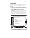
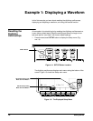
The display shows the probe compensation signal. It is a 1ĂkHz square wave
of approximately 0.5ĂV amplitude. You can adjust the size and placement of
the waveform using the frontĆpanel knobs.
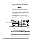
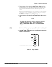
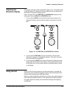
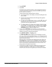
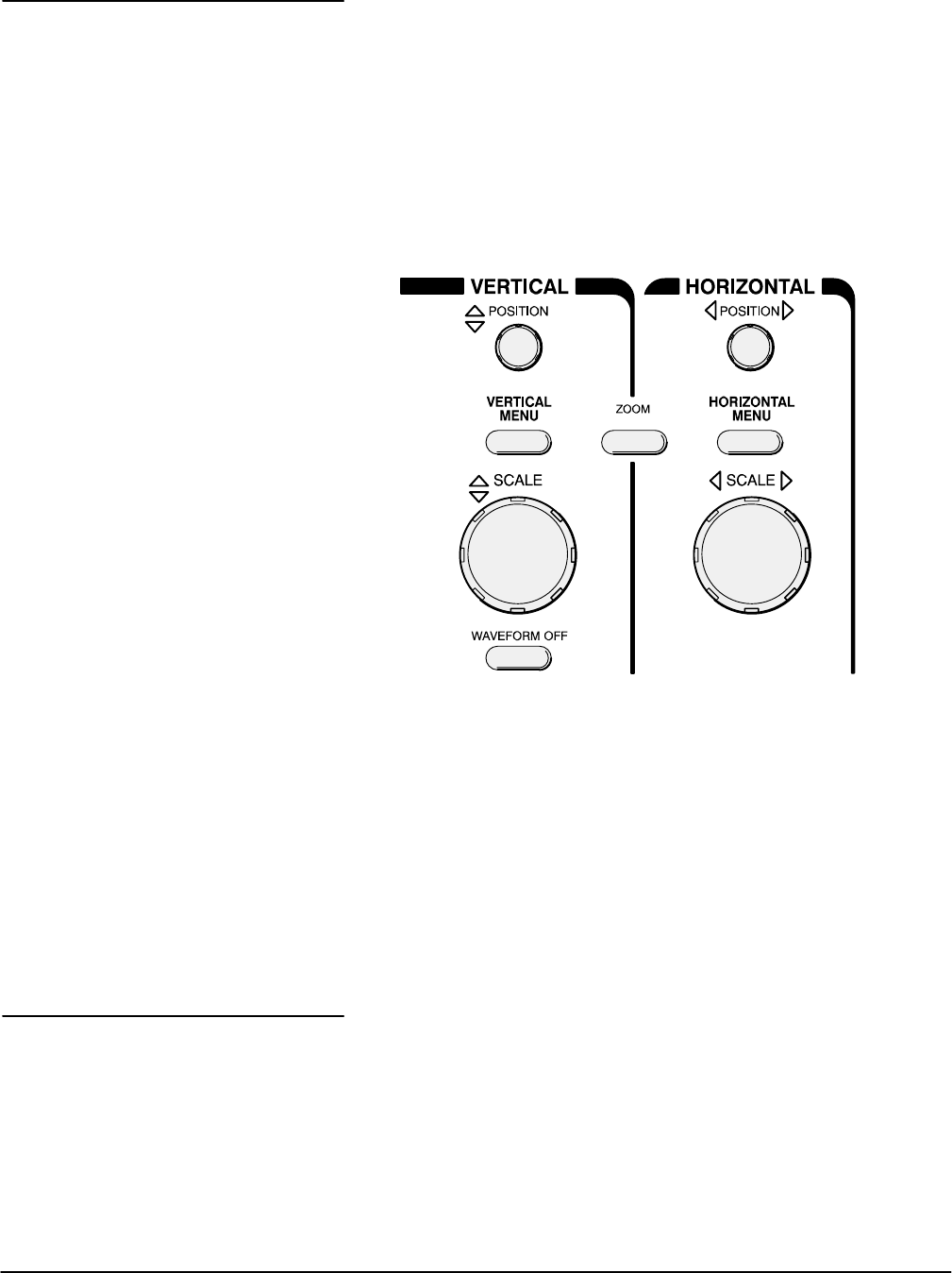
Figure 1Ć8 shows the main VERTICAL and HORIZONTAL sections of the
front panel. Each has SCALE and POSITION knobs.
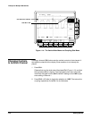
1. Turn the vertical SCALE knob clockwise. Observe the change in the
displayed waveform and the channel readout at the bottom of the disĆ
play.
Figure 1Ć8:ăThe VERTICAL and HORIZONTAL Controls
2. Turn the vertical POSITION knob first one direction, then the other.
Observe the change in the displayed waveform. Then return the waveĆ
form to the center of the graticule.
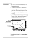
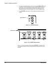
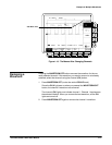
3. Turn the horizontal SCALE knob one click clockwise. Observe the time
base readout at the bottom of the display. The time base should be set
to 250Ăms/div now, and you should see two complete waveform cycles
on the display.
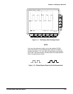
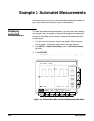
When you first connect a signal to a channel and display it, the signal disĆ
played may not be scaled and triggered correctly. Use the autoset function
and you should quickly get a meaningful display.
When you reset the digitizing oscilloscope, you see a clear, stable display of
the probe compensation waveform. That is because the probe compensaĆ
tion signal happens to display well at the default settings of the digitizing
oscilloscope.
Adjusting the
Waveform Display
Using Autoset