


Waveform Integration
Reference
3Ć146
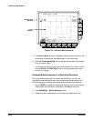
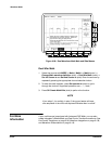
H Read the integrated voltage over time between the X of the selected
cursor and the reference indicator of the math waveform from the
@: readout.
H Read the time difference between the long vertical bars of the paired
cursors from the D: readout.
Automated Measurements of a Integral Waveform
You can also use automated measurements to measure integral math waveĆ
forms. Use the same procedure as is found under Waveform Differentiation
on page 3Ć140. When using that procedure, note that your measurements
on an integral waveform will be in voltĆseconds rather than in volts per
second as is indicated for the differential waveform measured in the proceĆ
dure.
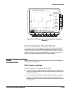
When creating integrated math waveforms from live channel waveforms,
consider the following topics.
Offset, Position, and Scale
Note the following requirements for obtaining a good display:
H You should scale and position the source waveform so it is contained on
screen. (Off screen waveforms may be clipped, which will result in errors
in the integral waveform).
H You can use vertical position and vertical offset to position your source
waveform. The vertical position and vertical offset will not affect your
integral waveform unless you position the source waveform off screen
so it is clipped.
H When using the vertical scale knob to scale the source waveform, note
that it also scales your integral waveform.
DC Offset
The source waveforms that you connect to the oscilloscope often have a DC
offset component. The oscilloscope integrates this offset along with the time
varying portions of your waveform. Even a few divisions of offset in the
source waveform may be enough to ensure that the integral waveform
saturates (clips), especially with long record lengths.
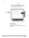
You may be able to avoid saturating your integral waveform if you choose a
shorter record length. (Press HORIZONTAL MENU ➞ Record
Length (main).) Reducing the sample rate (use the HORIZONTAL SCALE
knob) with the source channel selected might also prevent clipping. You can
also select AC coupling (on TDS models so equipped) in the vertical menu
of the source waveform or otherwise DC filter it before applying it to the
oscilloscope input.
Usage
Considerations