


Logic Triggering
Reference
3Ć76
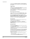
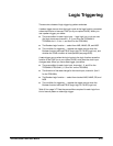
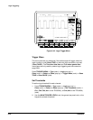
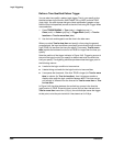
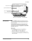
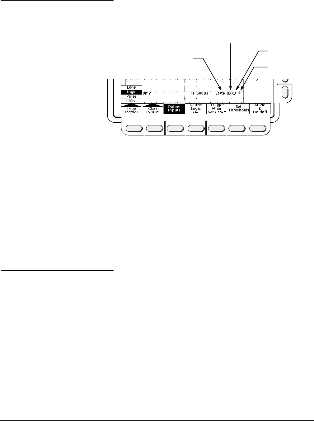
At the bottom of the display, the Trigger readout shows some of the key
parameters of the logic trigger (see Figure 3Ć41).
Trigger Class = State
Ch 1, 2, 3 Inputs = High, Don't Care, High
Ch 4 Input =
Rising Edge
Logic = OR
Figure 3Ć41:ăLogic Trigger Readouts
NOTE
When Logic is the selected trigger type, the threshold levels that
help determine triggering are set for each channel individually in
the Set Thresholds menu. Therefore, the Trigger Level readout will
disappear on the display and the Trigger Level knob can be used
to set the threshold level while the Main Trigger menu is set to
Logic.
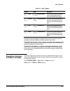
Table 3Ć3 lists the definitions for the four types of logic functions available.
Keep in mind the following operating modes for the two classes, pattern and
state, of logic triggers as you apply the definitions.
Pattern Ċ At the end of trigger holdoff, the oscilloscope samples the inputs
from all the channels. The oscilloscope then triggers if the conditions deĆ
fined in Table 3Ć3 are met. (Goes TRUE or Goes FALSE must be set in the
Trigger When menu. The other settings in that menu are described in
Define a Time Qualified Pattern Trigger on page 3Ć80.)
State Ċ At the end of trigger holdoff, the oscilloscope waits until the edge
of channel 4 (Aux 2 on the TDS 620A) transitions in the specified direction.
At that point, the oscilloscope samples the inputs from the other channels
and triggers if the conditions defined in Table 3Ć3 are met.
Logic Trigger
Readouts
Definitions