


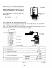
2) Pilot jet nozzle system
The pilot jet nozzle system controls the fuel supply for engine speeds ranging from idle to low-speed running. The
sytem operatzs with the
fuel
flowng through the main jet nozzle and up to the pilot jet nozzle where the tuel is
measured. When the fuel is mixed with air. the volume of the air-me1 mixture is also measurzd by the pilot air jet.
From this stage. the mixture is supphed to the engine t‘rom the pilot outlet and bb-pass. During idle.
fuel
is supplied
mainly from the pilot
outlet.
3) Main
jet
nozzle system
The main jet nozzle system supplies
fuel
for middle and high speed operation. The fuel flows to the main jet nozzle
where the fuel quantit) is measured. and then flows to the main nozzle. Air volume. which is measured by the main
air jet ~ enters from the bleed hole of the main nozzle and miszs with fuel to form a gas mist.
The gas mist flows out of the main bore and is again mixed with air from the air cleaner. From this stage. the correct
air-fu21 mixture is supplied to the engine.
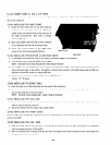
4)
Choke
The choke helps in starting the engine in cold weather.
When the engine is started with the choke valve closed. negative pressure applied to the main nozzle rises. allowing
most of fuel to flow through the main nozzle.
-4 mixture with a high gasoline concentration is fed to the engine resulting in easier engine starting.
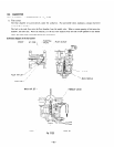
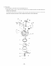
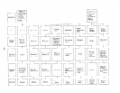
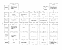
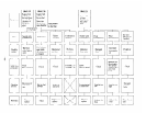
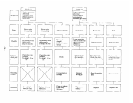
12-5-2 DISASSEMBLY and ASSEMBLY of CARBURETOR
The most common trouble with the carburstor is failure to provide the correct air-fuel mixture. This is generally caused bl-
blockage in the air and fuel channels. at other times it is caused by fuel level fluctuations in the float chamber. In order to
maintain the carburetor in normal operating condition. it is vital that the air and t‘uel channels be kept clean. The following
descriptions are the procedures for carburetor disassembly and assembly. (See Fig. 12-19.)
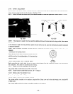
1) Throttle mechanism
a) Remove Philips-head screw (77): throttle valve
(~8),
and pull out the throttle shaft (39).
b) When removing the throttle stop screw. a spring (3 1
j
will also come off. Be careful when handling the throttle
valve to prevent the valve edge from damage.
2) Choke
a) Remove Philips-head screw (12). choke valve (23). and pull out choke shaft (24’).
b) Be sure to keep the notch of the choke valve positioned forward the main air jet side when the choke shaft is
installed.
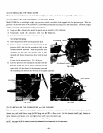
3) Pilot jet nozzle
a) Remove pilot jet nozzle (?I ). When removin,.
0 use a proper tool so that the nozzle will not be damaged.
b) Firmly secure the jet nozzle when the carburetor is assembled. Otherwise, fuel will leak from the nozzle and
cause engine trouble.
4) Main
jet
nozzle
a) Remove bolt (15). and float chamber bodl- ( 13).
b) Remove main jet nozzle ( 19) from carburetor bodk (9j.
c) Firmly secure the main jet nozzle when assembling. Othzrwise. air-fuel mixture will become excessiveIF rich and
the engine will not operate properly.
d) Torque for bolt (15) is 70 kg-cm.
-49-