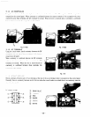
Sequence
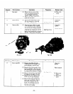
1 Part to remove
Description
Precautions
Necessary tools
12
Bas2 platz
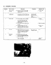
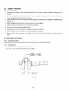
(1) Remove one set screw of the
T Plus screw-
earth wire which grounds the
; u
driver
rear housing and base
plate
I
togethsr (Zr)OV system onlv).
I
(2) Rsmove four 5115 x 10 bolts from
j
under the base plate.
Starter pullek
(1
13
Recoil starter
(1) Remove the recoil starter from
the rear housing. by removing
three 516 x 8 flange bolts.
j
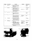
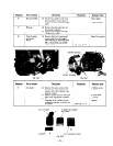
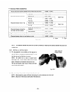
Turn the starter pulley b]- hand
to set the piston to the compres-
sion stroke limit (lvhere the pulle)
becomes heavy). Csing a hammer
strike the box wrench set ov2r the
I
head of the through bolt to remove
I
the bolt. Then remove the pulleb _
I
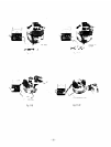
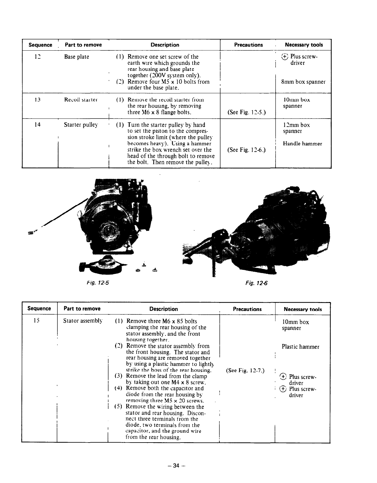
(See Fig. 12-S.)
(See Fig. 1 Z-6.)
Smm box spanner
1Omm box
spanner
1 ?mm box
spanner
Handle hammer
Fig. 12-5 Fig. 12-6
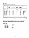
Sequence Part to remove
Description Precautions , Necessary tools
15
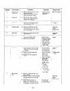
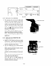
Stator assemblq- (1 j Remove three M6 x 85 bolts
clamping the rear housing of the
stator assembly. and the front
housing together.
(2j
Remove the stator assembly- from
the front housing. The stator and
rear housing are removed together
by using a plastic hammer to light11
strike the boss of the rzar housing.
(3)
Remove the lead from the clamp
I . .
b_~- taking out one M4 x 8 scre\v.
.
I
’ 1Omm box
spanner
Plastic hammer
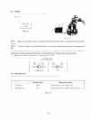
(See Fig. 12-7.) j
3 Plus screw-
_ driver
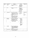
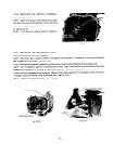
1 (4) Kemove both the capacitor and
I
: Cd Plus screw-
I
diode from the rear housing by
driver
I removing three M5 x 30 scre\\s.
/ (5) Remove the wiring between the
stator and rear housing. Discon-
i
nest three terminals irom the
diode. t\vo terminals from the
capacitor. and the ground \vire
from the r2ar housing.
-34 -


