


7. FUNCTION of EACH COMPONENT
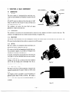
7-1 GENERATOR
7-1-1 STATOR
The stator consists of a laminated silicon steel sheet core,
a main coil and condenser coil which are wound in the core
slots.
AC and DC output are taken out from the main coil. (DC
output is taken out from the part of main coil which is in
the middle of the main coil.)
The condenser coil excites the stator field coil which
generates AC output in the main coil.
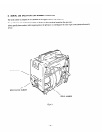
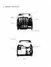
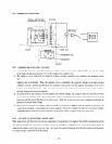
7-1-2 CONDENSER
REAR HOUSING
RECTIFIER
Fig. 7- 7
The condenser is mounted on the rear housing and is connected to the condenser coil which is wound in the stator. The
condenser coil magnetizes the rotor which increases the density of magnetic flux.
7-1-3 RECTIFIER
The rectifier is also mounted on the rear housing and it converts AC current output from the main coil to DC current. The
DC output from the diode of this rectifier is connected to the DC terminal.
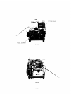
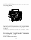
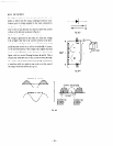
7-1-4 ROTOR
The rotor consists of a lamination silicon steel sheet core
and field coil which is wound over the core.
DC current m the field coil magnetizes the steel sheet core.
Two permanent magnets are provided at 90 degrees from
the poles for the primary exciting action.
A securely mounted fan is pressure-fitted on the end of the
rotor shaft to cool the individual coils. iron cores. rectifier.
and other integral parts.
Cooling air from the fan is drawn in from the ventilation
vents in the rear housing. and is discharged from the ex-
haust port in the front housing.
Fig. 7-2
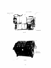
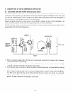
7-l-5 CONTROL PANEL
The panel on the front of the housing has a receptacle with
a ground terminal and AC output is taken out with a male
Plug.
The frequency meter is provided to see if the frequency of
generated power shows 50 Hz (or 60 Hz). DC output is
taken out from the red (positive. +) and black (.negative. -)
terminals.
-11-
Fig. 7-3