


.
*.
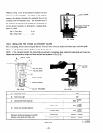
124-16 INSTALLING THE CENTER BAFFLE and FRONT HOUSING
1 j Set the knock hole of the front housing to the knock of the main bearing cover and assemble them together. During
assembly. place the center baffle between the main bearing cover and front housing.
Torque for the front housing: 80 - 100 kg-cm
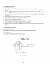
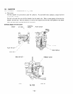
12-4-17 INSTALLING THE IGNITION COIL
1) Install the ignition coil and grommet (IG-COIL) to the front housing. Simultaneousl>-. temporarily set the generator
rotor in position.
-4nd assemble the ignition co11 and magnet together while adjusting the air gap between the two to
0.4 to 0.5 mm.
Firmly bond the grommet to the front ensuring that there is no residual clearance.
(use
CEMEDINE 575).
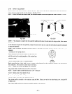
2) Fit the plug cap on the spark plug.
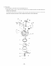
124-18 INSTALLING THE ROTOR ASSEMBLY
Install the rotor assembly to the taper of the crankshaft with their keyways in line.
NOTE: Thoroughly clean the tapers (both male and female tapers) of oily substances.
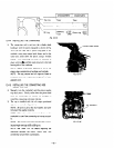
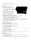
12-4-19 INSTALLING THE STATOR ASSEMBLY
1) Install the stator correctly into the recess of the rear housing. Sate the leads and their positions.
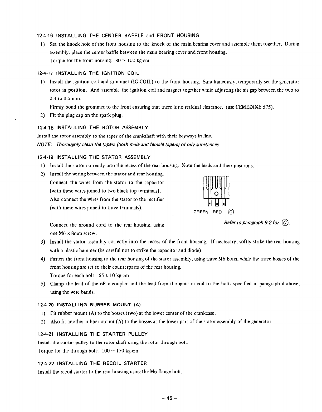
2) Install the wiring between the stator and rear housing.
Connect the wires from the stator IO the capacitor
(with these wires joined to two black top terminals).
Also connect the wires from the stator to the rectifier
(with these wires joined to three terminals).
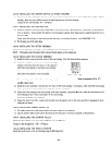
GREEN RED
:EJ
Connect the ground cord to the rear housing. using
Refer to paragraph 9-2 for @.
one M6 x 8mm screw.
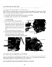
Install the stator assembly correctly into the recess of the front housing.
If necessary, softly strike the rear housing
with a plastic hammer (be careful not to strike the capacitor and diode).
Fasten the front housing to the rear housing of the stator assembly. using three M6 bolts, while the three bosses of the
front housing are set to their counterparts of the rear housing.
Torque for each bolt: 65 2 10 kg-cm
Clamp the lead of the 6P x coupler and the lead from the ignition coil to the bolts specified in paragraph
d
above.
using the wire bands.
124-20 INSTALLING RUBBER MOUNT (A)
1) Fit rubber mount (Aj to the bosses (two) at the lower center of the crankcase.
2) Also fit another rubber mount (A) to the bosses at the lower part of the stator assembly of the generator.
124-21 INSTALLING THE STARTER PULLEY
Install the starter pulle) to the rotor shaft using the rotor through bolt.
Torque for the through bolt: 100 - 150 kg-cm
124-22 INSTALLING THE RECOIL STARTER
Install the recoil starter to the rear housing using the M6 flange bolt.
-45-