


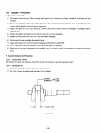
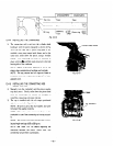
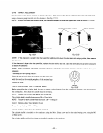
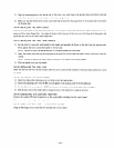
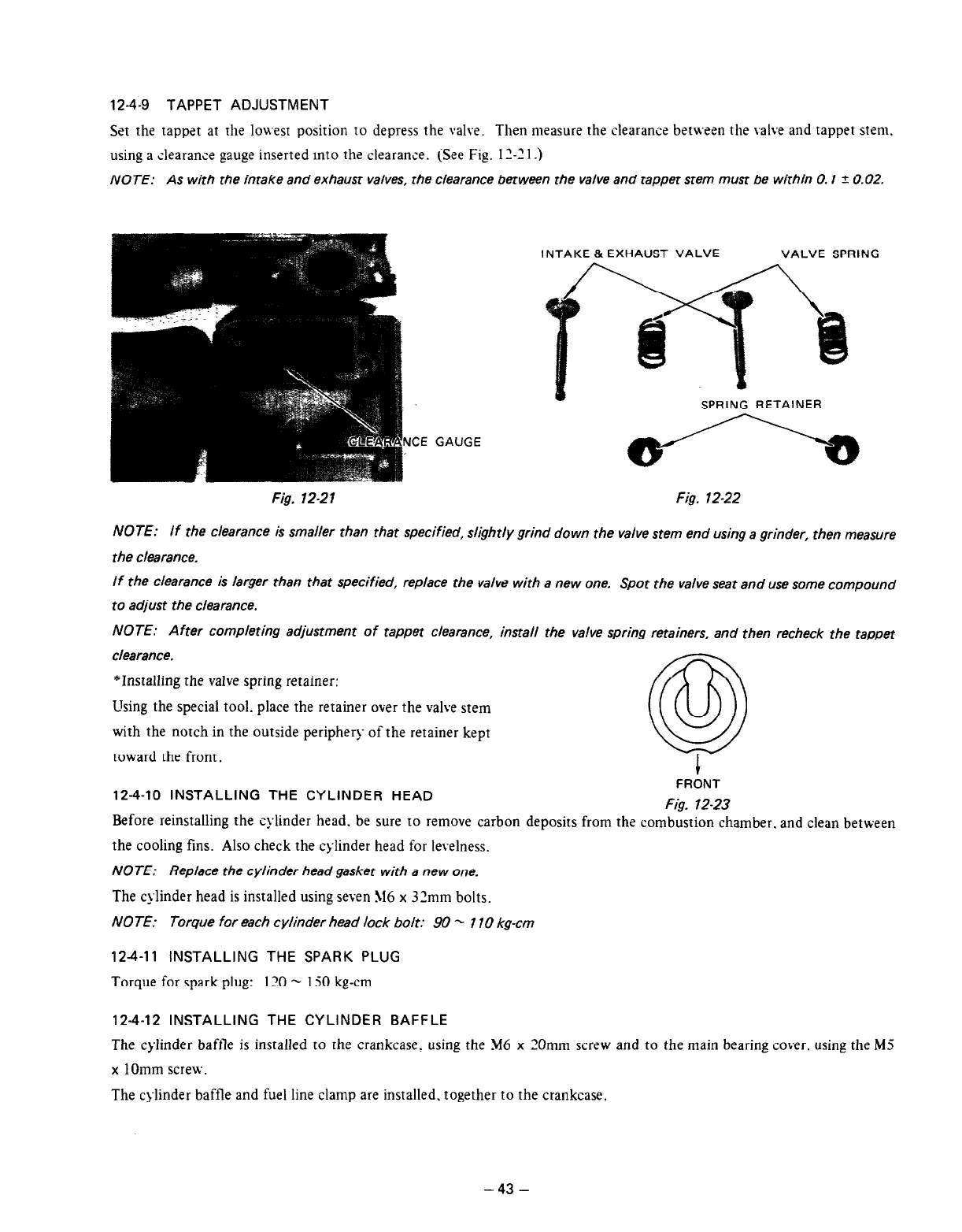
12-4-9 TAPPET ADJUSTMENT
Set
the tappet at
1112
loa-est position to depress the valve. Then measure the clearance
between
the valve and tappet stem.
using a clearance gauge inserted into the clearance. (See Fig. 12-21.)
NOTE: As with the intake and exhaust valves, the clearance between the valve and tappet stem must be within 0.1 f. 0.02.
INTAKE & EXHAUST VALVE
VALVE SPRING
NCE GAUGE
Fig. 12-27
Fig. 12-22
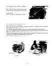
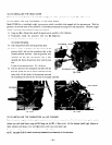
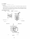
NOTE: If the clearance is smaller than that specified, slightly grind down the valve stem end using a grinder, then measure
the clearance.
If the clearance is larger than that specified, replace the valve with a new one.
Spot the valve seat and use some compound
to adjust the clearance.
NOTE: After completing adjustment of tapper clearance, install the valve spring retainers, and then recheck the tappet
clearance.
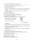
*Installing the valve spring retainer:
Using the special tool. place the retainer over the valve stem
with the notch in the outside periphery of the retainer kept
toward the front.
@
1
FRONT
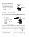
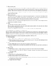
12-4-10 INSTALLING THE CYLINDER HEAD
Fig. 12-23
Before reinstalling the cylinder head.
be
sure to remove carbon deposits from the combustion chamber. and clean between
the cooling fins. Also check the cylinder head for levelness.
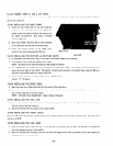
NOTE: Replace the cylinder head gasket with a new one.
The cylinder head is installed using seven 516 x 32mm bolts.
NOTE: Torque for each cylinder head lock bolt: 90 - 7 70 kg-cm
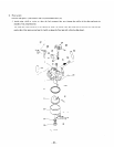
12-4-11 INSTALLING THE SPARK PLUG
Torque for spark plug: 120 - 130 kg-cm
12-4-12 INSTALLING THE CYLINDER BAFFLE
The
cylinder baffle is installed to the crankcase, using the M6 x 20mm screw and to the main bearing cover. using the M5
x 1Omm screw.
The cylinder baftle and
fuel
line clamp are installed. together to the crankcase.
-43 -