


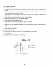
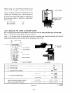
12-4-23 RUBBER TUBES for USE as AIR VENTS
Connect two rubber tubes to the air vent connectors of the carburetor. Keep theje rubber tubes suspended downward from
the air vent connectors.
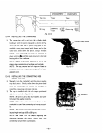
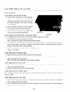
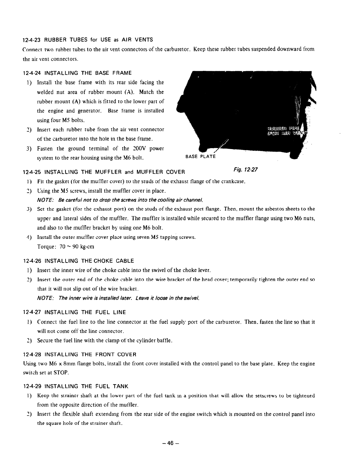
12-4-24 INSTALLING THE BASE FRAME
1)
Install the base frame with its rear side facing the
welded nut area of rubber mount (A). Match the
rubber mount (A) which is fitted to the lower part of
the engine and generator. Base frame is installed
using four MZ bolts.
3)
Insert each rubber tube from the air vent connector
of the carburetor into the hole in the base frame.
3)
Fasten the ground terminal of the ZOOV power
system to the rear housing using the $16 bolt.
-/
EASE PLATE
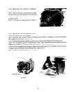
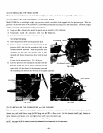
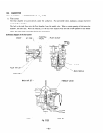
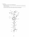
12-4-25 INSTALLING THE MUFFLER and MUFFLER COVER
Fig. 12-27
1) Fit the gasket (for the muffler cover) to the studs of the exhaust flange of the crankcase.
3) Using the 545 scre\vs, install the muffler cover in place.
NOTE: Be careful not to drop the screws into the cooling air channel.
3) Set the gasket (for the exhaust port) on the studs of the exhaust port flange. Then, mount the asbestos sheets to the
upper and lateral sides of the muffler. The muffler is installed while secured to the muffler flange using two M6 nuts,
and also to the muffler bracket by using one M6 bolt.
4)
Install the outer muffler cover place using seven MS tapping screws.
Torque: 70 - 90 kg-cm
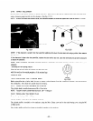
124-26 INSTALLING THE CHOKE CABLE
1) insert the inner wire of the choke cable into the swivel of the choke lever.
2) Insert the outer 2nd of the choke cable into the wire bracket of the head cover; temporarily tighten the outer end so
that it will not slip out of the uzir2 bracket.
NOTE: The inner wire is installed later. Leave it loose in the swivel.
12-4-27 INSTALLING THE FUEL LINE
1) Connect the fuel line to the line connector at the fuel supply port of the carburetor. Then. fasten the line so that it
will not come
oii
the line c’onn2ctor.
2) Secure the
fuel
line with the clamp of the cylinder baffle.
124-28 INSTALLING THE FRONT COVER
Using two h16 x 8mm flange bolts. install the front cover installed with the control pan21 to the base plate. Keep the engine
switch set at STOP.
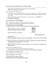
12-4-29 INSTALLING THE FUEL TANK
1
j
Keep the strainer shaft at the lower part of th2 fuel tank m a position that will allow the setscrews to be tightened
from the opposite direction of the muffler.
2) Insert the flexible shaft extendmg from the rear side of the engine switch which is mounted on the control panel into
the square hole of thr strainer shaft.
-46-